Tech Talk
Forum home - Go back to Tech talk
|
My first valve TV, and I need help please!
|
|
|
Return to top of page · Post #: 1 · Written at 9:34:54 PM on 26 January 2013.
|
|
|
|
Location: Wauchope, NSW
Member since 1 January 2013 Member #: 1269 Postcount: 576 |
|
Hi all, 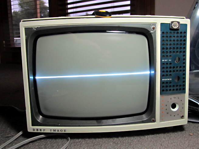 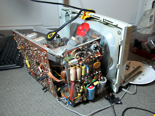 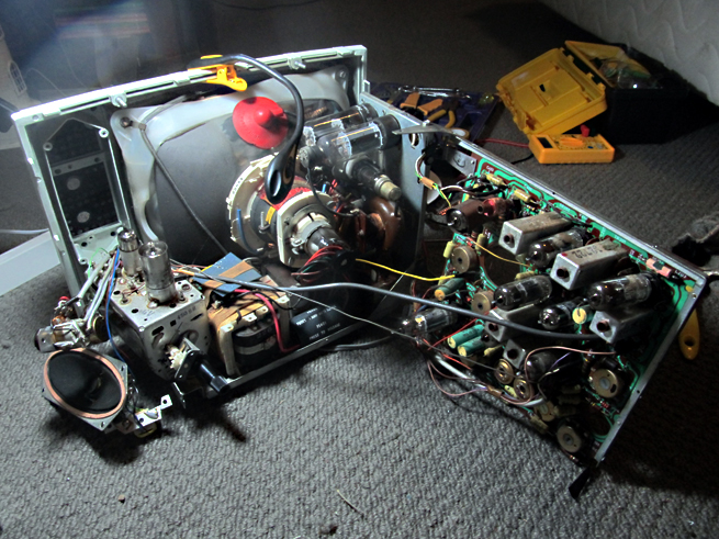 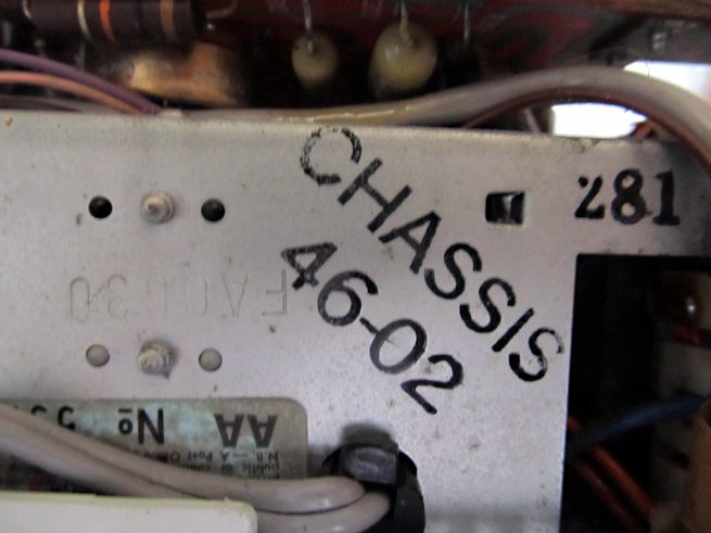 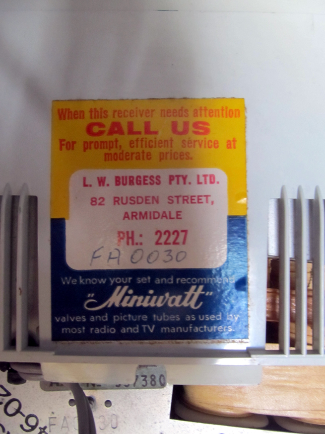 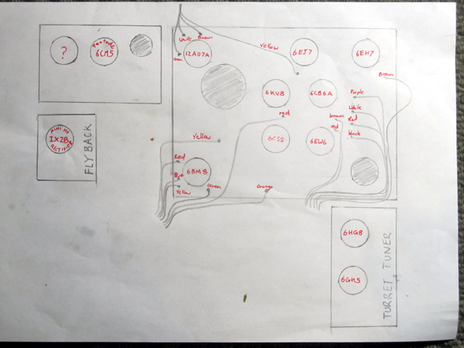 Thanks, Chris P.s. Where do you find the schematics for vintage televisions and radios? Is there a website or database for that? |
|
|
Return to top of page · Post #: 2 · Written at 12:19:01 PM on 27 January 2013.
|
|
|
|
Location: Melbourne, VIC
Member since 20 September 2011 Member #: 1009 Postcount: 1257 |
|
Hi Chris. |
|
|
Return to top of page · Post #: 3 · Written at 2:09:49 PM on 27 January 2013.
|
|
|
|
Location: Wauchope, NSW
Member since 1 January 2013 Member #: 1269 Postcount: 576 |
|
Hi Monochrome, |
|
|
Return to top of page · Post #: 4 · Written at 2:16:21 PM on 27 January 2013.
|
|
|
|
Location: Oradell, US
Member since 2 April 2010 Member #: 643 Postcount: 835 |
|
"The vertical deflection isn't covering the bottom of the screen. After all the CRT reading I've done, I'm thinking this could possibly be a valve issue" |
|
|
Return to top of page · Post #: 5 · Written at 7:53:49 PM on 27 January 2013.
|
|
|
|
Location: Melbourne, VIC
Member since 20 September 2011 Member #: 1009 Postcount: 1257 |
|
Hi Chris. |
|
|
Return to top of page · Post #: 6 · Written at 9:09:30 PM on 27 January 2013.
|
|
|
|
Administrator
Location: Naremburn, NSW
Member since 15 November 2005 Member #: 1 Postcount: 7567 |
|
Photos posted. ‾‾‾‾‾‾‾‾‾‾‾‾‾‾‾‾‾‾‾‾‾‾‾‾‾‾‾‾‾‾‾‾‾‾‾‾‾‾‾‾‾‾‾‾‾‾‾‾‾‾‾‾‾‾‾‾‾‾‾‾‾‾‾‾‾‾‾‾ A valve a day keeps the transistor away... |
|
|
Return to top of page · Post #: 7 · Written at 9:13:02 PM on 27 January 2013.
|
|
|
|
Location: Wauchope, NSW
Member since 1 January 2013 Member #: 1269 Postcount: 576 |
|
Hi Monochrome, thanks for that! Whenever you have the time is okay. My email address hasn't changed. |
|
|
Return to top of page · Post #: 8 · Written at 9:37:19 PM on 27 January 2013.
|
|
|
|
Administrator
Location: Naremburn, NSW
Member since 15 November 2005 Member #: 1 Postcount: 7567 |
|
A few tips:- ‾‾‾‾‾‾‾‾‾‾‾‾‾‾‾‾‾‾‾‾‾‾‾‾‾‾‾‾‾‾‾‾‾‾‾‾‾‾‾‾‾‾‾‾‾‾‾‾‾‾‾‾‾‾‾‾‾‾‾‾‾‾‾‾‾‾‾‾ A valve a day keeps the transistor away... |
|
|
Return to top of page · Post #: 9 · Written at 10:16:28 PM on 27 January 2013.
|
|
|
|
Location: Wauchope, NSW
Member since 1 January 2013 Member #: 1269 Postcount: 576 |
|
Brad, the image is now just a thinish line across the screen like in the photo. There is next to no vertical deflection. I'll be replacing the electrolytic caps as my next step in the project, so I'll hope this works. |
|
|
Return to top of page · Post #: 10 · Written at 11:19:17 PM on 27 January 2013.
|
|
|
|
Location: Melbourne, VIC
Member since 20 September 2011 Member #: 1009 Postcount: 1257 |
|
Chris. |
|
|
Return to top of page · Post #: 11 · Written at 11:54:25 PM on 27 January 2013.
|
|
|
|
Location: Wauchope, NSW
Member since 1 January 2013 Member #: 1269 Postcount: 576 |
|
Thank you for that Monochrome! I'll have a good look in the morning. It's far to late, and I should've been in bed and asleep a while ago. The joys of caffeine before bed... |
|
|
Return to top of page · Post #: 12 · Written at 9:42:47 AM on 28 January 2013.
|
|
|
|
Location: Ballarat, VIC
Member since 4 January 2011 Member #: 803 Postcount: 456 |
|
That's a nice clean little P1 on the inside. For a valve TV these tend to be fairly rugged and manage to stay working on the original parts despite being around 40 years old. |
|
|
Return to top of page · Post #: 13 · Written at 11:19:06 AM on 28 January 2013.
|
|
|
|
Location: Wauchope, NSW
Member since 1 January 2013 Member #: 1269 Postcount: 576 |
|
Thanks TV Collector. |
|
|
Return to top of page · Post #: 14 · Written at 12:02:29 PM on 28 January 2013.
|
|
|
|
Location: Melbourne, VIC
Member since 20 September 2011 Member #: 1009 Postcount: 1257 |
|
Hi Chris. |
|
|
Return to top of page · Post #: 15 · Written at 12:39:46 AM on 28 April 2013.
|
|
|
|
Location: Wauchope, NSW
Member since 1 January 2013 Member #: 1269 Postcount: 576 |
|
Hmm, I'll have to get around to getting this restored! I have so many other bloomin' sets to fix! I have some concerns that it may be a hefty job, as some of the components seem to have been changed with units of incorrect value (such as C319, which is rated for 100v instead of 1800v! It's a wonder it didn't blow... ). Still, it'll be a nice set once restored! |
|
|
You need to be a member to post comments on this forum.
|
|

Sign In

Vintage Radio and Television is proudly brought to you by an era where things were built with pride and made to last.
DISCLAIMER: Valve radios and televisions contain voltages that can deliver lethal shocks. You should not attempt to work on a valve radio or other electrical appliances unless you know exactly what you are doing and have gained some experience with electronics and working around high voltages. The owner, administrators and staff of Vintage Radio & Television will accept no liability for any damage, injury or loss of life that comes as a result of your use or mis-use of information on this website. Please read our Safety Warning before using this website.
WARNING: Under no circumstances should you ever apply power to a vintage radio, television or other electrical appliance you have acquired without first having it checked and serviced by an experienced person. Also, at no time should any appliance be connected to an electricity supply if the power cord is damaged. If in doubt, do not apply power.
Shintara - Keepin' It Real · VileSilencer - Maintain The Rage
