Welcome to Australia's only Vintage Radio and Television discussion forums. You are not logged in. Please log in below, apply for an account or retrieve your password.
Australian Vintage Radio Forums
  Home  ·  About Us  ·  Discussion Forums  ·  Glossary  ·  Outside Links  ·  Policies  ·  Services Directory  ·  Safety Warnings  ·  Tutorials

Tech Talk

Forum home - Go back to Tech talk

 Primary Short to Chassiss on an Astor BPJ
« Back · 1 · 2 · Next »
 Return to top of page · Post #: 1 · Written at 7:30:30 PM on 4 December 2025.
Hot Filiment's Gravatar
 Location: Castle Hill, NSW
 Member since 17 January 2025
 Member #: 2698
 Postcount: 46

I always do a safety check on any radio I get and before I start working in it. This radio was in it original state, though I am guessing the electrolyticsq and a few other caps had been changed back in the late 60s.

I found the primary of the power tranny seem to short with the chassis so I suspected the rotary power switch had a potential short on the chassis so I removed this and connected the power directly to the primary. Thereq was no earth line as it had the original 2 core power cable and I usually put a correct 3 core cable once I start the restoration.

I must not have been thinking clearly as I never confirmed that the power switch was the problem. I just assumed it was and proceeded with my usual powering up with the Dim bulb checking thr B+ and Bias etc Then with all valves in place the radio came toq life and it all seemed to be working with plenty of volume though it appear to make some crackling sounds like you get with mica decease in the IF cans.

I connected the arial to my common arial lug on my test bench and I triggered the Local And Main power safety swich how strange I thought.

Then It occurred to me that maybe the primary of the power transformer had a short to the chassis and that is exactly what I had found.

I had never encounter a short to the chassiss from the primary on what was a working power transformer. This surprised me.

My question are , is this common? How do I go about correcting this ? Or is the only way for a power transformer replacement?


 Return to top of page · Post #: 2 · Written at 9:22:23 PM on 4 December 2025.
Marcc's avatar
 Location: Wangaratta, VIC
 Member since 21 February 2009
 Member #: 438
 Postcount: 5691

In order to comply with new regulations and my own self preservation pre RCD's. I have a process, which I call "assessment". If it is a set for refurbishment and not known to work. It will be inspected.

It will not be immediately powered. I am well aware of the risks with monkeying, elderly unused caps and wire defects. The power primary and secondaries, will be checked and as it will eventually have to be done anyway. A "Pat Tester" or insulation tester will be used on the mains side & if there is suspicion all windings checked an also between each other. Exuberance powering first to see if it goes, is never step one, that can do a lot of damage & often I am expected to try & fix it.

One would need more info but it is not at all unusual for deteriorated wire to short. The fact that it is a two wire cord unless the chassis is grounded the RCD should not trip. However, CB's & fuses will fail. Wires will cut through on holes & big blobs of solder and debris is always an issue along with deteriorated wire.

The first step is to trace all of the wire associated with the mains primary. It usually ends up on a terminal strip and that set should have a double pole switch. What can happen if you did not replace, or check the filter caps, is that the filter caps will present as a short circuit usually destroying the rectifier or the HV primary. Initial test should never be with the rectifier in.

You need to isolate all of the transformers primary wires (three, Common; 200V; 260V) check them for damage, or deteriorated wiring which can short especially if its rubber, but should not be in 1958 but it can crack, get cut on unprotected holes, some ones stuffed up the wiring. or soldering it. The cable feeding it could also be faulty.

There should be no ohmic resistance of the primary to ground. Regulation insulation test is a 500V DC. Need to see what type of transformer construction it is.


 Return to top of page · Post #: 3 · Written at 8:02:00 PM on 5 December 2025.
Robbbert's avatar
 Location: Hill Top, NSW
 Member since 18 September 2015
 Member #: 1801
 Postcount: 2246

You could have a careful look at the transformer and see if there's any wires touching the frame.

Or, (not recommended), you could isolate the transformer from the chassis and cover it to stop someone from touching it.

To do it properly you'd have to replace it, but it's a big job, even if you have a replacement that fits.


 Return to top of page · Post #: 4 · Written at 8:05:28 PM on 5 December 2025.
Hot Filiment's Gravatar
 Location: Castle Hill, NSW
 Member since 17 January 2025
 Member #: 2698
 Postcount: 46

Thanks Marcc ,
Agree with your points and usually follow a strict safety checks along the lines you suggest.
I did however make a poor assumption assuning the power on rotary switch was the source of the short.

I have removed the transformer from the radio and have confirm a short in fact exist between the primary windings and the 6.3V dial lamps and valve filament transformer windings. I will be considering take off the windings of the 6.3V supply which are the top layer and then the primary to see if I can isolate where the short exist and hopefully put it back together.

Not had such a problem before so another learning experience.

Cheers


 Return to top of page · Post #: 5 · Written at 9:02:31 PM on 5 December 2025.
Johnny's avatar
 Location: Hobart, TAS
 Member since 31 July 2016
 Member #: 1959
 Postcount: 599

I find it hard to believe that a short would be possible between the mains primary winding and the secondary filament winding.
That is, an internal short. Its more likely to be a short between these windings at the entry and exit points.
So, close inspection of the wires going into and out of the transformer is required.
Before one pulls it all apart, and it becomes a "point of no return" repair.
In my experience shorts as described are very, very rare. Unless caused externally.
JJ


 Return to top of page · Post #: 6 · Written at 9:58:12 PM on 5 December 2025.
Marcc's avatar
 Location: Wangaratta, VIC
 Member since 21 February 2009
 Member #: 438
 Postcount: 5691

I am inclined to agree with Johnny. In order for a short of that magnitude, the transformer has to have internally fried and I have yet to see one do that. I have posted one in a Thorn where the secondary melted down, but not the primary, nor heater winding. There have been regulations re-construction since the 1930's.

We need a photo of it. It is as I noted not unusual to get wire cuts & insulation fails and if its got "bells" it could short inside that: Seen it. We need to see the wire. And if the transformer is out: All wire.

Agree this is odd.

I do sometimes Insulation test between windings, But in nearly five decades, have never had one, even those with a burnt winding short between windings, it always been something else

The only way the transformer could like the Thorn have a catastrophic melt down is being left on with a secondary short.


 Return to top of page · Post #: 7 · Written at 1:31:07 PM on 6 December 2025.
Hot Filiment's Gravatar
 Location: Castle Hill, NSW
 Member since 17 January 2025
 Member #: 2698
 Postcount: 46

Thank you for your comments, I will send some pictures to Brad, but I can assure I have tested out of the radio on the bench with a mega and the short does not exist with the metal frame of the transformer.
One end of the primary red wire has a direct short with 6.3v winding the other end black wire is about 40ohms with thec6.3v winding, So I am expecting the problem to be close to the entry of the red wire but it is not where the it connect with the fine copper wire of the primary from what I can see.
The is no evidence of it having a melt down and all other parts of the transformer work and voltages are as expected.

I was at the HRSA meeting today and was lucky, a member had a NOS stock transformer of similar speccwhich I bought.

I will however begin this arvo with the investigation to find the failure point and will send photos to Brad for upload if you are interested.


 Return to top of page · Post #: 8 · Written at 10:33:35 PM on 6 December 2025.
Marcc's avatar
 Location: Wangaratta, VIC
 Member since 21 February 2009
 Member #: 438
 Postcount: 5691

Looking at the transformer of the Astor JJ there is every chance with wiring insulation deterioration, which has been addressed on this one.

Externally the mains can touch a filament / heater winding.

Some of the Philips transformers had a nasty habit of winding wires exiting the wrap on the side, that is also fixable.


 Return to top of page · Post #: 9 · Written at 8:16:39 AM on 7 December 2025.
Hot Filiment's Gravatar
 Location: Castle Hill, NSW
 Member since 17 January 2025
 Member #: 2698
 Postcount: 46

I have sent some pictures to Brad and found the problem. You last post Marcc was correct.

The mains red wire you will see in the pics once uploaded,
runs under the filament coil winding and is connected to the copper primary winding by a solder joint and tucked back in under the primary winding, I guess this produces a possible weak insulation point with only paper and the vanish insulation on the filament to insulate it.

Once I pulled out the the soldered connecting piece from under the filament coil, the short disappeared.
So I use some heat shrink over the this exposed area but chose to not push it back under the filament coil, I did the same with the 220 wire and the green wire as the could easily have the same problem in the future.

I tested all again with mega to 1000V no shorts between any of the coils were found. Yippee.

So the good news is I can refit this transformer with some confidence, the bad new is the rotary power switch which I originally suspected as a problem disintegrated when I tried to put it back together,it was already intermittently failing as they do.

So I need to find a replacement dedicated rotary switch compatible with the knob, any suggestions?

Astor transformer
Astor transformer
Astor transformer


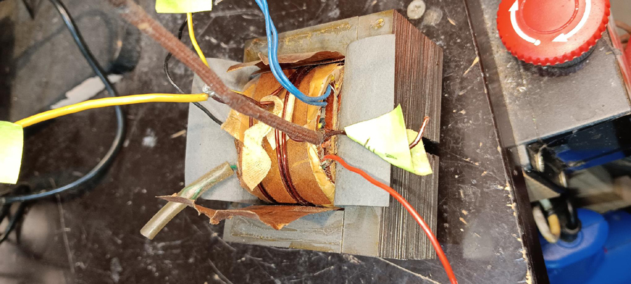
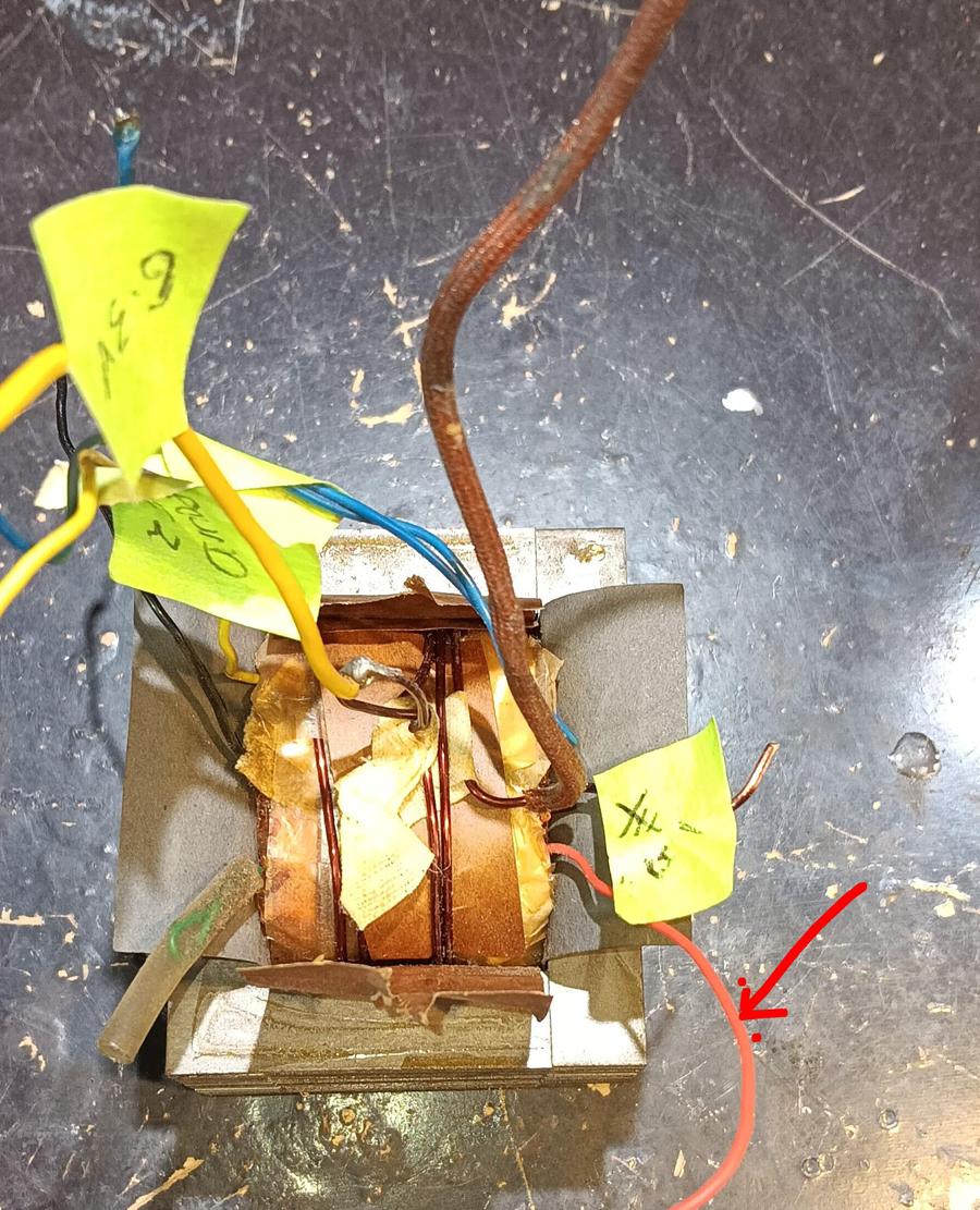
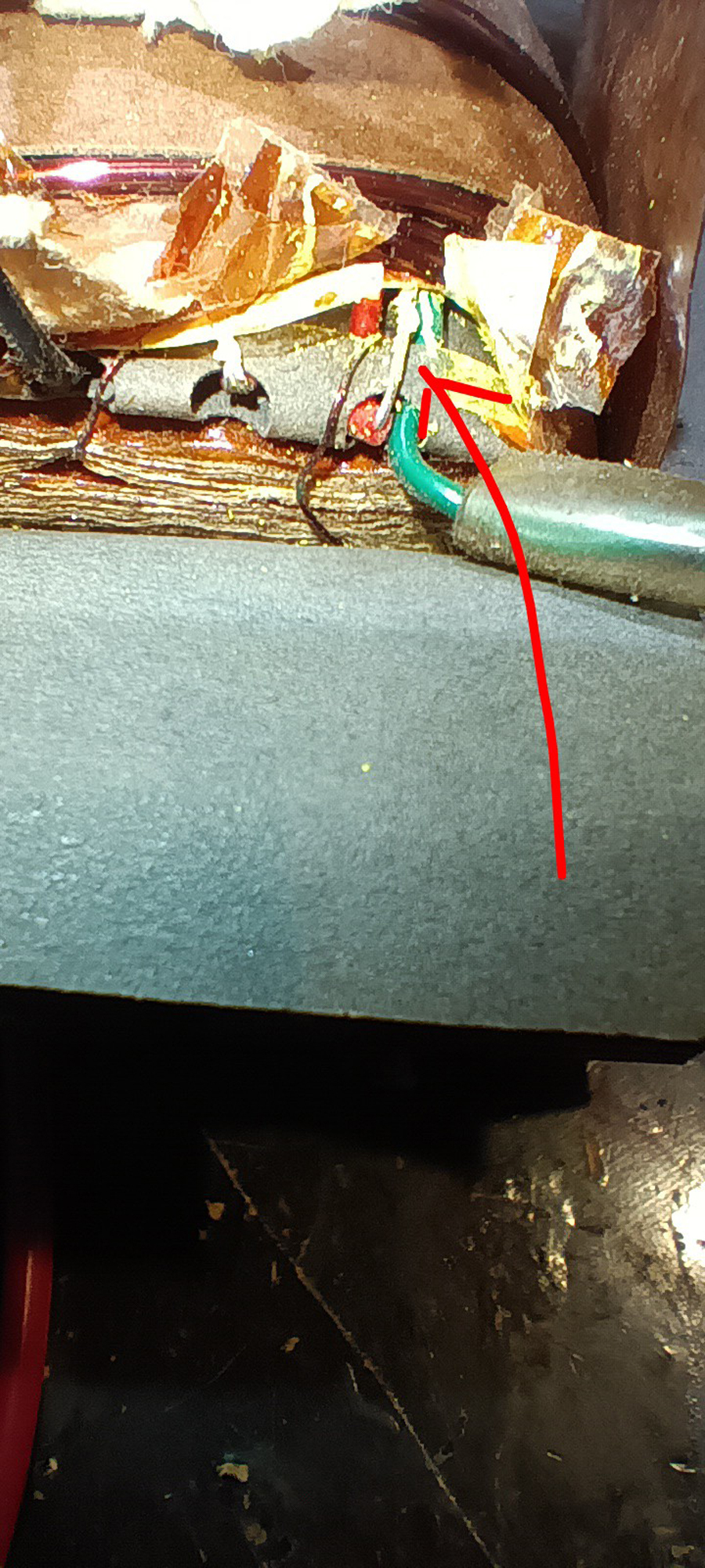
 Return to top of page · Post #: 10 · Written at 9:01:22 AM on 7 December 2025.
Marcc's avatar
 Location: Wangaratta, VIC
 Member since 21 February 2009
 Member #: 438
 Postcount: 5691

I would think it an idea, that once you have shrink tube between the two offending wires, that you use something like Araldite or a terminal strip in the pan to ensure the wires are captive. Araldite was suggested for the Philips transformer, by a motor rewinder.

There is also "CRC Urethane Seal Coat" Generator winding coating insulation. Code 2044 is red. There is another clear. I quite often use it on coils to re-seal them.

You can if you want use the Insulation Tester to prove the Non Polarised paper caps, were not worth the trouble testing. Do not touch the Mica ones on coils. Mica is usually fairly reliable, in general, despite the odd failure: Leave well alone.

As far as I am concerned any NP cap that leaks is a dud. Spec is under 50Meg no good as a screen decoupling cap and under 200Meg no good as a coupling cap. I do not understand the thinking, of those who leave old leaky waxed paper caps in sets.

I get paid to fix them and will not do it. Nearing five decades of fixing says at this point in time. Time is better spent replacing them than testing them when I know that over 99%will fail.

The electrolytics can be tested & I have reached the point of doing that with allegedly new ones before use. If you replace electrolytics you replace all of them.


 Return to top of page · Post #: 11 · Written at 11:09:24 AM on 8 December 2025.
Trobbins's avatar
 Location: Melbourne, VIC
 Member since 11 July 2012
 Member #: 1179
 Postcount: 65

I'm looking forward to seeing the photos of the location of the short, and the factory mechanism of terminating the mains wiring and 'tucking it back in'.

Hot Filiment, it sounds like that factory wire/termination method may be difficult to recognise by just visual inspection?

I also pedantically retest the mains after any rework (however trivial), before doing any energisation. Sparkies are responsible for doing a set of tests (visual, continuity and IR at 500V) for any altered mains circuit, including relocated equipment which has previously been factory tested (as the equipment may have incurred some travel related fault). There are often more passive changes that can be made to lessen the risk of mains insulation related faults, but at least as a minimum the process of visual, continuity and IR based tests is well worth doing by everyone.


 Return to top of page · Post #: 12 · Written at 3:07:06 PM on 8 December 2025.
Marcc's avatar
 Location: Wangaratta, VIC
 Member since 21 February 2009
 Member #: 438
 Postcount: 5691

Doing the "Tag & Test" thing on stuff, turns up an interesting array of faults from inverted wires on cables to some things that are just plain deadly.

I will send Brad a mains side photo of the Astor "JJ" transformer. This is an old repair, initiated by failing mainly eroding wire, or low grade rubber disintegrating.

We have a heavy current winding very close to mains wire, where it would have taken little encouragement for bare wires to meet. A lot of that early lacquer is brittle and now cannot be wound.

Astor transformer


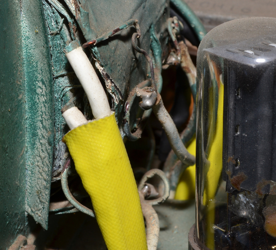
 Return to top of page · Post #: 13 · Written at 2:27:20 PM on 9 December 2025.
Hot Filiment's Gravatar
 Location: Castle Hill, NSW
 Member since 17 January 2025
 Member #: 2698
 Postcount: 46

I sent the photos to Brad on the 7th Dec. Brad did you get these or do I need to resend. The email I used this time based on what is listed in contact admistrator, I note is different to what had use back in Sept?

Cheers George


 Return to top of page · Post #: 14 · Written at 3:17:33 PM on 9 December 2025.
Brad's avatar
 Administrator
 Location: Naremburn, NSW
 Member since 15 November 2005
 Member #: 1
 Postcount: 7612

No need to resend. I have been out of town and all photos will go up today.


‾‾‾‾‾‾‾‾‾‾‾‾‾‾‾‾‾‾‾‾‾‾‾‾‾‾‾‾‾‾‾‾‾‾‾‾‾‾‾‾‾‾‾‾‾‾‾‾‾‾‾‾‾‾‾‾‾‾‾‾‾‾‾‾‾‾‾‾
A valve a day keeps the transistor away...

 
 Return to top of page · Post #: 15 · Written at 11:00:49 PM on 9 December 2025.
Brad's avatar
 Administrator
 Location: Naremburn, NSW
 Member since 15 November 2005
 Member #: 1
 Postcount: 7612

Photos uploaded to Posts 9 and 12.


‾‾‾‾‾‾‾‾‾‾‾‾‾‾‾‾‾‾‾‾‾‾‾‾‾‾‾‾‾‾‾‾‾‾‾‾‾‾‾‾‾‾‾‾‾‾‾‾‾‾‾‾‾‾‾‾‾‾‾‾‾‾‾‾‾‾‾‾
A valve a day keeps the transistor away...

 
« Back · 1 · 2 · Next »
 You need to be a member to post comments on this forum.

Sign In

Username:
Password:
 Keep me logged in.
Do not tick box on a computer with public access.