
Tech Talk
Forum home - Go back to Tech talk
|
The loving 6BV7
|
|
|
Return to top of page · Post #: 1 · Written at 9:42:02 PM on 7 February 2025.
|
|
|
|
Location: Geelong, VIC
Member since 12 July 2018 Member #: 2266 Postcount: 47 |
|
Some may remember the 6BV7 was used in the 1956 Lt General from Radio & Hobbies. It ran exceedingly hot and burnt me a few times on that build. |
|
|
Return to top of page · Post #: 2 · Written at 11:18:55 PM on 7 February 2025.
|
|

|
Location: Hill Top, NSW
Member since 18 September 2015 Member #: 1801 Postcount: 2145 |
|
This valve has been mentioned a number of times recently. |
|
|
Return to top of page · Post #: 3 · Written at 2:25:04 AM on 8 February 2025.
|
|

|
Location: Sydney, NSW
Member since 28 January 2011 Member #: 823 Postcount: 6843 |
-- UQ Physics Museum |
|
|
Return to top of page · Post #: 4 · Written at 6:29:38 PM on 8 February 2025.
|
|
|
|
Location: Geelong, VIC
Member since 12 July 2018 Member #: 2266 Postcount: 47 |
|
As Quoted by The Manufacture July,1952 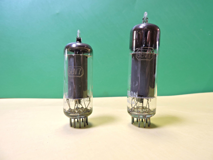 AWV 6BV7 Valve |
|
|
Return to top of page · Post #: 5 · Written at 8:06:53 PM on 8 February 2025.
|
|
|
|
Location: Toongabbie, NSW
Member since 19 November 2015 Member #: 1828 Postcount: 1353 |
|
Yes, just enter '6BV7' in the search forum on this site to get an earful! |
|
|
Return to top of page · Post #: 6 · Written at 8:09:48 PM on 8 February 2025.
|
|

|
Location: Wangaratta, VIC
Member since 21 February 2009 Member #: 438 Postcount: 5511 |
|
If you want to stick with that valve & its a heat issue & most output tubes & rectifiers run seriously hot; Consider fan forced air from a CPU fan, under it. |
|
|
Return to top of page · Post #: 7 · Written at 8:07:02 AM on 9 February 2025.
|
|
|
|
Location: Belrose, NSW
Member since 31 December 2015 Member #: 1844 Postcount: 2556 |
|
Or increase the bias. |
|
|
Return to top of page · Post #: 8 · Written at 8:18:49 AM on 9 February 2025.
|
|

|
Administrator
Location: Naremburn, NSW
Member since 15 November 2005 Member #: 1 Postcount: 7486 |
|
An interesting stat - the rectifier and output valves were usually located side by side and at the rear of the radio to allow their heat to dissipate. All valves get hot but these two got hotter than most. It was an important consideration since many radio cabinets were inflammable. ‾‾‾‾‾‾‾‾‾‾‾‾‾‾‾‾‾‾‾‾‾‾‾‾‾‾‾‾‾‾‾‾‾‾‾‾‾‾‾‾‾‾‾‾‾‾‾‾‾‾‾‾‾‾‾‾‾‾‾‾‾‾‾‾‾‾‾‾ A valve a day keeps the transistor away... |
|
|
Return to top of page · Post #: 9 · Written at 9:00:32 AM on 9 February 2025.
|
|
|
|
Location: Wangaratta, VIC
Member since 21 February 2009 Member #: 438 Postcount: 5511 |
|
Hot tubes and their placement, for me has been a constant problem. Many have a bad habit of destroying their sockets, which I replace with ceramic. On plastic sets they can eventually cause the plastic above them to lose plasticity & crack or distort. |
|
|
Return to top of page · Post #: 10 · Written at 9:28:43 AM on 9 February 2025.
|
|
|
|
Location: Belrose, NSW
Member since 31 December 2015 Member #: 1844 Postcount: 2556 |
|
Getting back to the 6BV7... |
|
|
Return to top of page · Post #: 11 · Written at 10:50:26 PM on 9 February 2025.
|
|
|
|
Location: Wangaratta, VIC
Member since 21 February 2009 Member #: 438 Postcount: 5511 |
|
I would expect changes to the back bias to have an effect on all tubes. You may need to recalculate & add a conventional cathode resistor, for self bias. The voltage drop across the back bias resistor will tell you the current for the whole set: Unaltered. |
|
|
Return to top of page · Post #: 12 · Written at 5:20:47 PM on 10 February 2025.
|
|
|
|
Location: Belrose, NSW
Member since 31 December 2015 Member #: 1844 Postcount: 2556 |
|
Marcus, the 6BV7 is a very high slope bottle. So doubling the back bias resistor will not double the total back bias as you might think, just increase it slightly, probably by about 1 volt max. |
|
|
Return to top of page · Post #: 13 · Written at 9:06:35 PM on 10 February 2025.
|
|

|
Location: Melbourne, VIC
Member since 20 September 2011 Member #: 1009 Postcount: 1235 |
|
|
|
|
Return to top of page · Post #: 14 · Written at 9:11:46 PM on 10 February 2025.
|
|
|
|
Location: Wangaratta, VIC
Member since 21 February 2009 Member #: 438 Postcount: 5511 |
|
I am not intending to double the back bias. I was considering applying that to the other tubes only to maintain their design parameters and adding conventional self bias to the 6BV7 by adding a cathode resistor and bypass cap. |
|
|
Return to top of page · Post #: 15 · Written at 5:34:23 PM on 11 February 2025.
|
|
|
|
Location: Belrose, NSW
Member since 31 December 2015 Member #: 1844 Postcount: 2556 |
|
Much simpler to just double the back bias resistor and get the result with far less modification. |
|
|
You need to be a member to post comments on this forum.
|
|
 Ian
IanSign In
Vintage Radio and Television is proudly brought to you by an era where things were built with pride and made to last.
DISCLAIMER: Valve radios and televisions contain voltages that can deliver lethal shocks. You should not attempt to work on a valve radio or other electrical appliances unless you know exactly what you are doing and have gained some experience with electronics and working around high voltages. The owner, administrators and staff of Vintage Radio & Television will accept no liability for any damage, injury or loss of life that comes as a result of your use or mis-use of information on this website. Please read our Safety Warning before using this website.
WARNING: Under no circumstances should you ever apply power to a vintage radio, television or other electrical appliance you have acquired without first having it checked and serviced by an experienced person. Also, at no time should any appliance be connected to an electricity supply if the power cord is damaged. If in doubt, do not apply power.
Shintara - Keepin' It Real · VileSilencer - Maintain The Rage