Tech Talk
Forum home - Go back to Tech talk
|
Raycophone 63AE - Beale Panchromatic
|
|
|
Return to top of page · Post #: 1 · Written at 6:44:18 PM on 26 July 2019.
|
|
|
|
Location: Mount Lawley, WA
Member since 12 September 2017 Member #: 2167 Postcount: 49 |
|
I acquired this set last week. 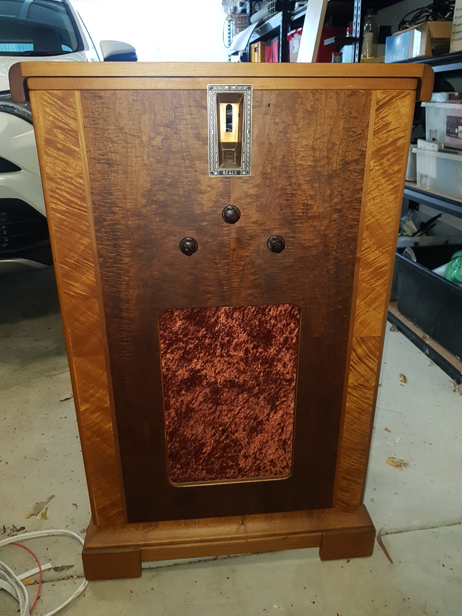 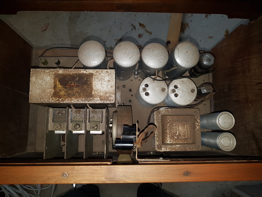 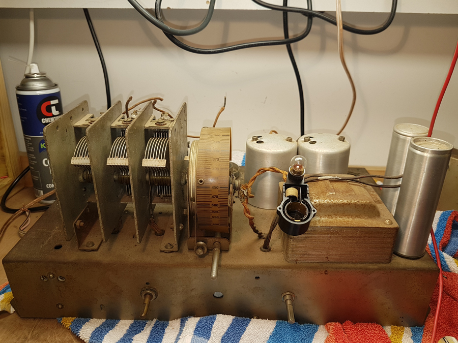 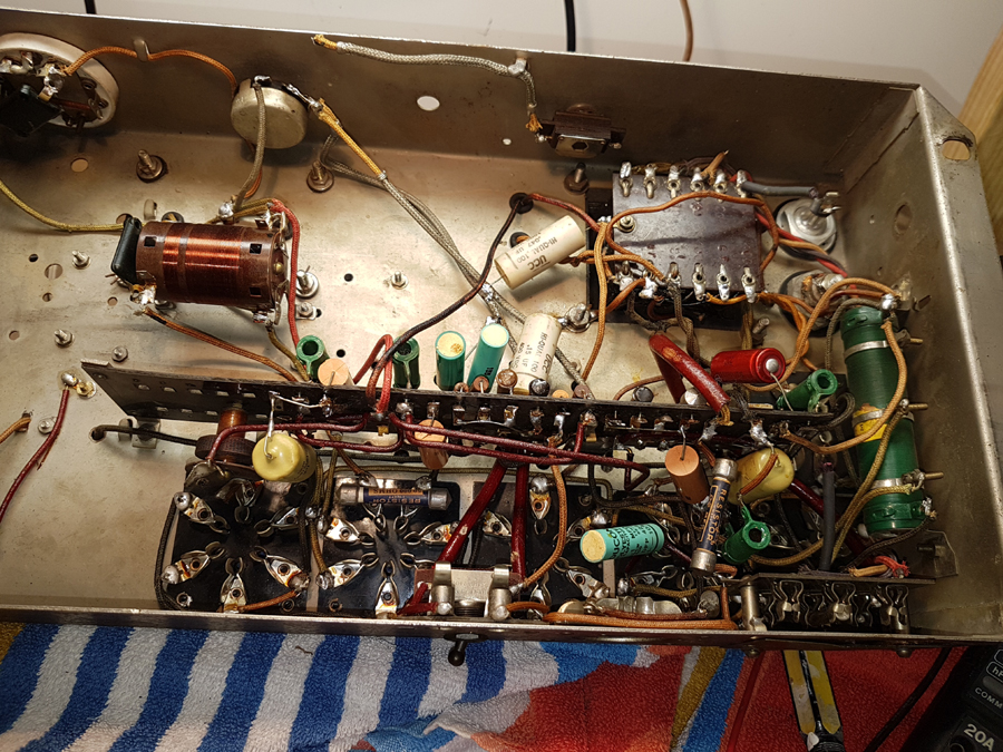 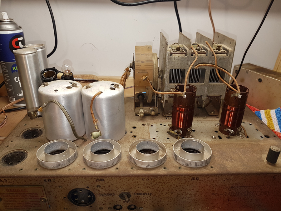 Raycophone 63AE Circuit Diagram |
|
|
Return to top of page · Post #: 2 · Written at 9:18:37 PM on 26 July 2019.
|
|
|
|
Location: Wangaratta, VIC
Member since 21 February 2009 Member #: 438 Postcount: 5595 |
|
Where there is a TRF stage I have had one of those ? moments when it was realised that there was a choke in series with the plate & the varmint had gone open. It was I assure you not meant to couple. |
|
|
Return to top of page · Post #: 3 · Written at 9:46:39 PM on 26 July 2019.
|
|
|
|
Location: NSW
Member since 10 June 2010 Member #: 681 Postcount: 1370 |
|
There is a good article on tuning indicators in Radiomuseum: |
|
|
Return to top of page · Post #: 4 · Written at 11:32:51 PM on 26 July 2019.
|
|
|
|
Location: Wangaratta, VIC
Member since 21 February 2009 Member #: 438 Postcount: 5595 |
|
With the 6B7 fitted it is possibly a micro ammeter tied into some form of AGC. I think we await a circuit. There are likely explanations in some books I have here, as there are some written in that era. It is a good idea to keep an eye out for such things, should you want to understand how they work. |
|
|
Return to top of page · Post #: 5 · Written at 10:17:10 AM on 27 July 2019.
|
|
|
|
Location: Mount Lawley, WA
Member since 12 September 2017 Member #: 2167 Postcount: 49 |
|
Thanks for your comments guys. |
|
|
Return to top of page · Post #: 6 · Written at 10:51:07 AM on 27 July 2019.
|
|
|
|
Location: Brisbane, QLD
Member since 18 September 2010 Member #: 102 Postcount: 301 |
|
Does your radio have a top that opens to expose the valves, I had one years ago, mine had a 1934 STC chassis in a Beale Panchromatic cabinet. |
|
|
Return to top of page · Post #: 7 · Written at 1:38:35 PM on 27 July 2019.
|
|
|
|
Location: Mount Lawley, WA
Member since 12 September 2017 Member #: 2167 Postcount: 49 |
|
Hi Rudolf. |
|
|
Return to top of page · Post #: 8 · Written at 1:59:13 PM on 27 July 2019.
|
|
|
|
Location: Brisbane, QLD
Member since 18 September 2010 Member #: 102 Postcount: 301 |
|
It's a long time since I had it, you're right mine would have had 2 or 3 knobs. |
|
|
Return to top of page · Post #: 9 · Written at 4:30:23 PM on 27 July 2019.
|
|
|
|
Location: Milton, NSW
Member since 27 June 2016 Member #: 1945 Postcount: 56 |
|
Don't know about Weston but could the tuning indicator be a saturated reactor type? These typically have a lamp in series with a special form of iron cored inductance, in the plate circuit of an AVC controlled valve. |
|
|
Return to top of page · Post #: 10 · Written at 9:21:41 PM on 27 July 2019.
|
|
|
|
Administrator
Location: Naremburn, NSW
Member since 15 November 2005 Member #: 1 Postcount: 7548 |
|
The lid is a definite Beale giveaway - there were a couple of Beale-badged radios with that top. If your Raycophone is anything like mine it will weigh as much as a tank. They were well made and Raycophone should have been in business far longer than they were. ‾‾‾‾‾‾‾‾‾‾‾‾‾‾‾‾‾‾‾‾‾‾‾‾‾‾‾‾‾‾‾‾‾‾‾‾‾‾‾‾‾‾‾‾‾‾‾‾‾‾‾‾‾‾‾‾‾‾‾‾‾‾‾‾‾‾‾‾ A valve a day keeps the transistor away... |
|
|
Return to top of page · Post #: 11 · Written at 11:04:56 AM on 28 July 2019.
|
|
|
|
Location: Mount Lawley, WA
Member since 12 September 2017 Member #: 2167 Postcount: 49 |
|
Thanks Brad. |
|
|
Return to top of page · Post #: 12 · Written at 2:29:23 PM on 28 July 2019.
|
|
|
|
Location: Cameron Park, NSW
Member since 5 November 2010 Member #: 770 Postcount: 425 |
|
My guess at the operation of the tuning indicator is....... |
|
|
Return to top of page · Post #: 13 · Written at 10:07:05 PM on 28 July 2019.
|
|
|
|
Administrator
Location: Naremburn, NSW
Member since 15 November 2005 Member #: 1 Postcount: 7548 |
|
My apologies for forgetting the link to the circuit diagram. The link to this is now below the photos. In accordance with recent tradition, I have converted this to a PDF so members can enlarge it for easier reading. ‾‾‾‾‾‾‾‾‾‾‾‾‾‾‾‾‾‾‾‾‾‾‾‾‾‾‾‾‾‾‾‾‾‾‾‾‾‾‾‾‾‾‾‾‾‾‾‾‾‾‾‾‾‾‾‾‾‾‾‾‾‾‾‾‾‾‾‾ A valve a day keeps the transistor away... |
|
|
Return to top of page · Post #: 14 · Written at 11:18:47 PM on 28 July 2019.
|
|
|
|
Location: Wangaratta, VIC
Member since 21 February 2009 Member #: 438 Postcount: 5595 |
|
Ok! Whist looking for info on a cable oscillator, I found reference to the Indicators. In days of old we had no AGC. We had the “Grid Leak” and then the Plate detector. In the grid leak type on the arrival of a signal the Plate current in a Grid leak falls. With the “Plate detector: aka Anode bend it rides. Therefore, a sensitive current meter in the Plate circuit, or in the case of the latter, a neon tube, can be used to indicate the best tuning. |
|
|
Return to top of page · Post #: 15 · Written at 6:35:50 PM on 10 August 2019.
|
|
|
|
Location: Belrose, NSW
Member since 31 December 2015 Member #: 1844 Postcount: 2629 |
|
Yes well spotted Marc. Those white UCCs are indeed paper ("Hi_Qual" = paper, "DiPol" = polyester). |
|
|
You need to be a member to post comments on this forum.
|
|

Sign In

Vintage Radio and Television is proudly brought to you by an era where things were built with pride and made to last.
DISCLAIMER: Valve radios and televisions contain voltages that can deliver lethal shocks. You should not attempt to work on a valve radio or other electrical appliances unless you know exactly what you are doing and have gained some experience with electronics and working around high voltages. The owner, administrators and staff of Vintage Radio & Television will accept no liability for any damage, injury or loss of life that comes as a result of your use or mis-use of information on this website. Please read our Safety Warning before using this website.
WARNING: Under no circumstances should you ever apply power to a vintage radio, television or other electrical appliance you have acquired without first having it checked and serviced by an experienced person. Also, at no time should any appliance be connected to an electricity supply if the power cord is damaged. If in doubt, do not apply power.
Shintara - Keepin' It Real · VileSilencer - Maintain The Rage
