
Special Projects
Forum home - Go back to Special Projects
|
Electronics Australia EA160 SSB Receiver
|
|
|
Return to top of page · Post #: 1 · Written at 11:01:35 AM on 21 August 2016.
|
|

|
Location: Daylesford, VIC
Member since 13 January 2011 Member #: 809 Postcount: 326 |
|
I've decided to try making this "budget" SSB project from EA December 1970, which failed to work the first time round when my Dad and I attempted to build the kit; it's not the kind of project that's likely to be successful without test gear handy, something which the designer Ian Pogson glosses over in the original article. It's a double-conversion set with a 4-8MHz tunable first IF, covering from 550kHz to 24MHz in 4MHz-wide bands. Second IF is 455kHz and uses three of those little red box ceramic resonators from Murata. (That bit I've already built and tested.) The 4-8MHz band is direct, the others via a fixed first oscillator (not crystal, but could be made so easily) on 4, 8, 12, and 16MHz. There are going to be a couple of nasty spurious signals at 4 and 8MHz, that seems unavoidable; hopefully the direct 4-8 range can be made to cover the unusable areas of the adjacent ranges. One thing I can improve on is the uncalibrated manual RF tuning, which needs an accurate dial and a slow-motion drive, otherwise you don't know if you've tuned in on the correct frequency or an image. The top RF tuning range is 8 to 24MHz, four whole 4MHz bands on one small unmarked knob! Please bear with me on this project, because it's at my limit of understanding and I'll have a few questions to ask. 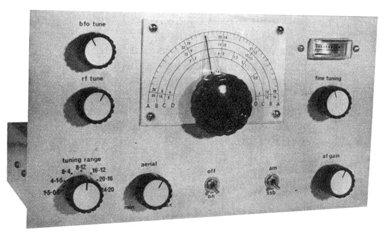 |
|
|
Return to top of page · Post #: 2 · Written at 7:44:49 PM on 21 August 2016.
|
|
|
|
Location: Daylesford, VIC
Member since 13 January 2011 Member #: 809 Postcount: 326 |
|
OK, the first question. I know that in an audio amp it's usual to earth the circuit to the chassis only at the at the input connectors to avoid hum loops. In an HF receiver, do you instead earth each circuit tagstrip to the nearby chassis, and not bother with a negative wire from the power supply? It's hard to tell how they've arranged this in the prototype. |
|
|
Return to top of page · Post #: 3 · Written at 8:11:22 PM on 21 August 2016.
|
|

|
Location: Sydney, NSW
Member since 28 January 2011 Member #: 823 Postcount: 6949 |
|
I was taught to always keep the number of chassis common earthing points to one (star connection), on the basis that every such connection has a resistance and variations in resistance create ground loops and associated noise. |
|
|
Return to top of page · Post #: 4 · Written at 7:36:42 PM on 22 August 2016.
|
|
|
|
Location: Ballarat, VIC
Member since 4 January 2011 Member #: 803 Postcount: 456 |
|
If most of the circuit is built on tagstrip I'd use the mounting terminal of each strip as a local ground point. As long as you are using a metal chassis, there will be no issues in doing this. Running a separate 0v line to the tagstrips will probably introduce instability into the circuit due to all the extra stray inductance and capacitance of the various 0v wires. |
|
|
Return to top of page · Post #: 5 · Written at 9:54:25 PM on 11 September 2016.
|
|

|
Administrator
Location: Naremburn, NSW
Member since 15 November 2005 Member #: 1 Postcount: 7624 |
|
Photo and circuit diagram uploaded. ‾‾‾‾‾‾‾‾‾‾‾‾‾‾‾‾‾‾‾‾‾‾‾‾‾‾‾‾‾‾‾‾‾‾‾‾‾‾‾‾‾‾‾‾‾‾‾‾‾‾‾‾‾‾‾‾‾‾‾‾‾‾‾‾‾‾‾‾ A valve a day keeps the transistor away... |
|
|
Return to top of page · Post #: 6 · Written at 2:03:36 PM on 13 September 2016.
|
|
|
|
Location: Daylesford, VIC
Member since 13 January 2011 Member #: 809 Postcount: 326 |
|
I've completed and tested the RF strip, and this part has problems. The fact that it's far more sensitive at 1 MHz than 24 MHz isn't surprising, but the gain is so high at 1 MHz it oscillates. The 47 ohm resistor across the aerial winding of L1 was obviously added to stop this, but there's still a big peak in the middle of the MW band. Maybe it'll be OK once the AGC is working and the strip is earthed to a chassis. I've changed the 100 pF coupling capacitors to 10 pF and 20 pF to reduce the gain on MW. 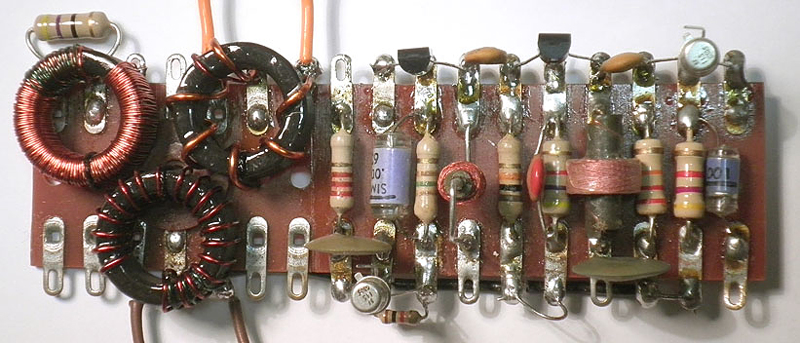 |
|
|
Return to top of page · Post #: 7 · Written at 11:08:06 PM on 13 September 2016.
|
|
|
|
Location: Sydney, NSW
Member since 28 January 2011 Member #: 823 Postcount: 6949 |
|
I tried to look for errors and errata for that project, but cannot even find the original article in the EA index on the SC site. I guess that index is deficient. |
|
|
Return to top of page · Post #: 8 · Written at 8:14:22 AM on 14 September 2016.
|
|
|
|
Location: NSW
Member since 10 June 2010 Member #: 681 Postcount: 1407 |
|
The original article can be found through. |
|
|
Return to top of page · Post #: 9 · Written at 10:50:16 AM on 14 September 2016.
|
|
|
|
Location: Sydney, NSW
Member since 28 January 2011 Member #: 823 Postcount: 6949 |
|
Back in those days of typeset printing technology many of their projects contained errors and omissions that were reported months afterwards. |
|
|
Return to top of page · Post #: 10 · Written at 6:49:52 PM on 14 September 2016.
|
|
|
|
Location: Daylesford, VIC
Member since 13 January 2011 Member #: 809 Postcount: 326 |
|
I haven't seen errata for this project, but I've not many issues from 1971 where you'd expect to find them. |
|
|
Return to top of page · Post #: 11 · Written at 5:24:48 PM on 15 September 2016.
|
|
|
|
Administrator
Location: Naremburn, NSW
Member since 15 November 2005 Member #: 1 Postcount: 7624 |
|
Photo uploaded to Post 6. ‾‾‾‾‾‾‾‾‾‾‾‾‾‾‾‾‾‾‾‾‾‾‾‾‾‾‾‾‾‾‾‾‾‾‾‾‾‾‾‾‾‾‾‾‾‾‾‾‾‾‾‾‾‾‾‾‾‾‾‾‾‾‾‾‾‾‾‾ A valve a day keeps the transistor away... |
|
|
Return to top of page · Post #: 12 · Written at 6:07:30 PM on 15 September 2016.
|
|
|
|
Location: Sydney, NSW
Member since 28 January 2011 Member #: 823 Postcount: 6949 |
|
Okay, I've blown the dust of my 1971 and 1972 issues and here is what I found in Notes & Errata: |
|
|
Return to top of page · Post #: 13 · Written at 11:43:56 AM on 18 September 2016.
|
|
|
|
Location: Daylesford, VIC
Member since 13 January 2011 Member #: 809 Postcount: 326 |
|
Ta GTC. I spotted the error on the RF diagram while I was making the RF strip. I presume the 0.01μF 160V listed are meant to be Philips mustard tubular, because one of these is visible in the close up photo of L6. I've got some, but they'd be a very tight fit on the first oscillator board; 0.01μF 100V greencap polyesters would be better. Would using those make any difference to the oscillator? |
|
|
Return to top of page · Post #: 14 · Written at 1:14:40 PM on 18 September 2016.
|
|
|
|
Location: Sydney, NSW
Member since 28 January 2011 Member #: 823 Postcount: 6949 |
|
There are so many 'poly' type caps around these days that I cannot keep up with them. |
|
|
Return to top of page · Post #: 15 · Written at 10:48:01 PM on 19 September 2016.
|
|
|
|
Location: Daylesford, VIC
Member since 13 January 2011 Member #: 809 Postcount: 326 |
|
EA normally used the Philips mustards in the prototypes of their projects in those days, and I think 160V was the lowest voltage the Philips came in. The Elna greencap polys were much smaller, but they were fairly new, not made in Australia, and perhaps not trusted by the designers. I don't know if greencaps are different in construction or worse for RF; I'll give them a try as you suggest. |
|
|
You need to be a member to post comments on this forum.
|
|
Sign In
Vintage Radio and Television is proudly brought to you by an era where things were built with pride and made to last.
DISCLAIMER: Valve radios and televisions contain voltages that can deliver lethal shocks. You should not attempt to work on a valve radio or other electrical appliances unless you know exactly what you are doing and have gained some experience with electronics and working around high voltages. The owner, administrators and staff of Vintage Radio & Television will accept no liability for any damage, injury or loss of life that comes as a result of your use or mis-use of information on this website. Please read our Safety Warning before using this website.
WARNING: Under no circumstances should you ever apply power to a vintage radio, television or other electrical appliance you have acquired without first having it checked and serviced by an experienced person. Also, at no time should any appliance be connected to an electricity supply if the power cord is damaged. If in doubt, do not apply power.
Shintara - Keepin' It Real · VileSilencer - Maintain The Rage