
Special Projects
Forum home - Go back to Special Projects
|
A one valve superhet with a 6Y9
|
|
|
Return to top of page · Post #: 16 · Written at 8:28:58 PM on 10 September 2022.
|
|
|
|
Location: Toongabbie, NSW
Member since 19 November 2015 Member #: 1828 Postcount: 1404 |
|
I made a start on the project coming up with a chassis. |
|
|
Return to top of page · Post #: 17 · Written at 2:08:36 PM on 11 September 2022.
|
|

|
Administrator
Location: Naremburn, NSW
Member since 15 November 2005 Member #: 1 Postcount: 7618 |
|
Document uploaded. ‾‾‾‾‾‾‾‾‾‾‾‾‾‾‾‾‾‾‾‾‾‾‾‾‾‾‾‾‾‾‾‾‾‾‾‾‾‾‾‾‾‾‾‾‾‾‾‾‾‾‾‾‾‾‾‾‾‾‾‾‾‾‾‾‾‾‾‾ A valve a day keeps the transistor away... |
|
|
Return to top of page · Post #: 18 · Written at 7:48:18 PM on 11 September 2022.
|
|
|
|
Location: Belrose, NSW
Member since 31 December 2015 Member #: 1844 Postcount: 2706 |
|
Fred I really appreciate your interest in this. It's been rattling around in my head for years but there's always been too much else that needed to be done for me to attack a real build. 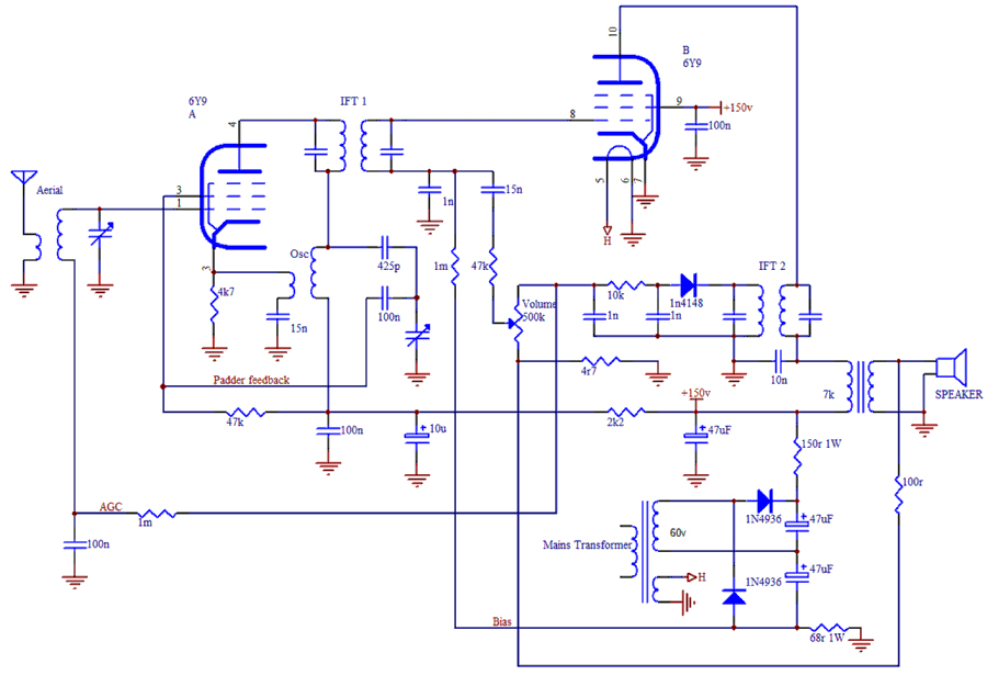 I don't know if the way I've connected the padder feedback will work, we don't have the luxury with an Autodyne of a "cold" oscillator coil winding. My thinking is, if this thing works, it would be nice if it worked well. Oh, another thing. Back in the day the company I worked for had a rental fleet of Philips TVs that used 6Y9s. The 6Y9 had a habit of flashing over G2 to G1 and G3. This would take out the video detector diode and the "Set White" pot in the cathode. We found it paid to reduce HT4 from 180 volts to 150 volts with a bigger dropper resistor. That also allowed the other notoriously short life Decal valves (6X9, 6U9) in the IFs to last a lot longer. So I think the B+ should be 150V.  On reflection the way I've tried to achieve padder feedback probably won't help. I think we'll just ground the 100nF and hope the better gain of the 6Y9 does the job. |
|
|
Return to top of page · Post #: 19 · Written at 7:07:15 AM on 12 September 2022.
|
|
|
|
Location: Toongabbie, NSW
Member since 19 November 2015 Member #: 1828 Postcount: 1404 |
|
Thanks Ian, I take note about the HT value. |
|
|
Return to top of page · Post #: 20 · Written at 6:33:00 PM on 13 September 2022.
|
|
|
|
Administrator
Location: Naremburn, NSW
Member since 15 November 2005 Member #: 1 Postcount: 7618 |
|
Photos uploaded to Post 18. ‾‾‾‾‾‾‾‾‾‾‾‾‾‾‾‾‾‾‾‾‾‾‾‾‾‾‾‾‾‾‾‾‾‾‾‾‾‾‾‾‾‾‾‾‾‾‾‾‾‾‾‾‾‾‾‾‾‾‾‾‾‾‾‾‾‾‾‾ A valve a day keeps the transistor away... |
|
|
Return to top of page · Post #: 21 · Written at 10:20:55 PM on 13 September 2022.
|
|
|
|
Location: Belrose, NSW
Member since 31 December 2015 Member #: 1844 Postcount: 2706 |
|
Thanks Brad. |
|
|
Return to top of page · Post #: 22 · Written at 5:24:18 PM on 14 September 2022.
|
|
|
|
Administrator
Location: Naremburn, NSW
Member since 15 November 2005 Member #: 1 Postcount: 7618 |
|
I use Photoshop 7 for most image touch ups. It has similar features as listed above. ‾‾‾‾‾‾‾‾‾‾‾‾‾‾‾‾‾‾‾‾‾‾‾‾‾‾‾‾‾‾‾‾‾‾‾‾‾‾‾‾‾‾‾‾‾‾‾‾‾‾‾‾‾‾‾‾‾‾‾‾‾‾‾‾‾‾‾‾ A valve a day keeps the transistor away... |
|
|
Return to top of page · Post #: 23 · Written at 1:38:07 AM on 15 September 2022.
|
|

|
Location: Wangaratta, VIC
Member since 21 February 2009 Member #: 438 Postcount: 5703 |
|
If you want to avoid messing with the antenna circuit, the front end could become an autodyne (screen grid) & control the self bias, by way of the cathode. |
|
|
Return to top of page · Post #: 24 · Written at 7:16:39 AM on 15 September 2022.
|
|
|
|
Location: Toongabbie, NSW
Member since 19 November 2015 Member #: 1828 Postcount: 1404 |
|
Hi Marc, thanks for suggestion re the front end. |
|
|
Return to top of page · Post #: 25 · Written at 8:41:41 PM on 15 September 2022.
|
|
|
|
Location: Belrose, NSW
Member since 31 December 2015 Member #: 1844 Postcount: 2706 |
|
Hi Fred, Marc |
|
|
Return to top of page · Post #: 26 · Written at 11:18:15 PM on 21 September 2022.
|
|

|
Location: Hill Top, NSW
Member since 18 September 2015 Member #: 1801 Postcount: 2250 |
|
How's this project coming along? |
|
|
Return to top of page · Post #: 27 · Written at 6:58:45 AM on 22 September 2022.
|
|
|
|
Location: Toongabbie, NSW
Member since 19 November 2015 Member #: 1828 Postcount: 1404 |
|
Hi Rob and all. |
|
|
Return to top of page · Post #: 28 · Written at 9:59:09 AM on 22 September 2022.
|
|
|
|
Location: Belrose, NSW
Member since 31 December 2015 Member #: 1844 Postcount: 2706 |
|
Well done Fred! |
|
|
Return to top of page · Post #: 29 · Written at 12:42:27 PM on 22 September 2022.
|
|

|
Location: Hobart, TAS
Member since 31 July 2016 Member #: 1959 Postcount: 603 |
|
Talking about transistors, one of our local amateur radio enthusiasts some time ago built and got working a one transistor HF transceiver. |
|
|
Return to top of page · Post #: 30 · Written at 2:12:17 PM on 22 September 2022.
|
|
|
|
Location: Belrose, NSW
Member since 31 December 2015 Member #: 1844 Postcount: 2706 |
|
I remember 2 transistor 27MHz super-regen handheld transceivers in the early 60s. They actually worked, kinda! |
|
|
You need to be a member to post comments on this forum.
|
|

Sign In
Vintage Radio and Television is proudly brought to you by an era where things were built with pride and made to last.
DISCLAIMER: Valve radios and televisions contain voltages that can deliver lethal shocks. You should not attempt to work on a valve radio or other electrical appliances unless you know exactly what you are doing and have gained some experience with electronics and working around high voltages. The owner, administrators and staff of Vintage Radio & Television will accept no liability for any damage, injury or loss of life that comes as a result of your use or mis-use of information on this website. Please read our Safety Warning before using this website.
WARNING: Under no circumstances should you ever apply power to a vintage radio, television or other electrical appliance you have acquired without first having it checked and serviced by an experienced person. Also, at no time should any appliance be connected to an electricity supply if the power cord is damaged. If in doubt, do not apply power.
Shintara - Keepin' It Real · VileSilencer - Maintain The Rage