
Workshops, Tools and Test Equipment
Forum home - Go back to Workshops, Tools and Test Equipment
|
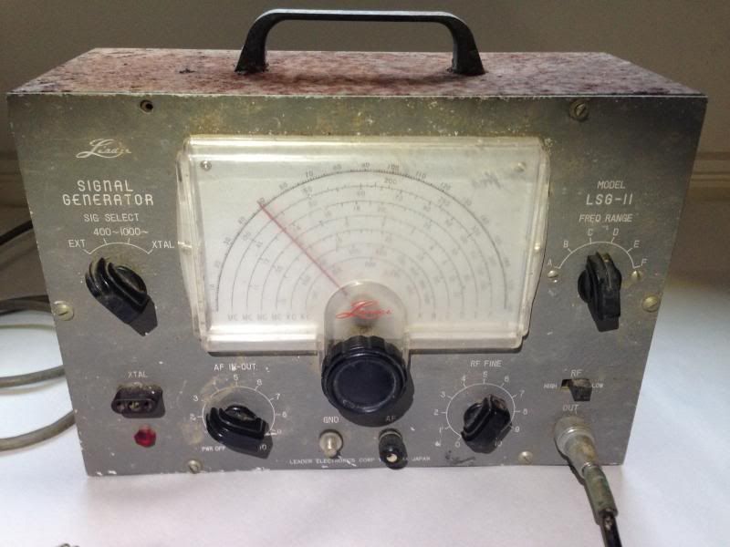
Valve Signal Generator
|
|
|
Return to top of page · Post #: 1 · Written at 9:03:22 PM on 16 January 2014.
|
|
|
|
Location: Somewhere, USA
Member since 22 October 2013 Member #: 1437 Postcount: 896 |
|
Hi Guys, |
|
|
Return to top of page · Post #: 2 · Written at 1:09:23 AM on 17 January 2014.
|
|

|
Location: Sydney, NSW
Member since 28 January 2011 Member #: 823 Postcount: 6956 |
|
They sold lots of LSG-11s. I have one and it stays on frequency very well. |
|
|
Return to top of page · Post #: 3 · Written at 2:20:51 AM on 17 January 2014.
|
|
|
|
Location: Somewhere, USA
Member since 22 October 2013 Member #: 1437 Postcount: 896 |
|
Thanks that's nice to know, because I do like it, and it's cleaning up well. |
|
|
Return to top of page · Post #: 4 · Written at 8:21:09 AM on 17 January 2014.
|
|
|
|
Location: Canberra, ACT
Member since 23 August 2012 Member #: 1208 Postcount: 587 |
|
Is that socket marked "xtal" an output of crystal freq, or an input for external crystal? |
|
|
Return to top of page · Post #: 5 · Written at 10:07:13 AM on 17 January 2014.
|
|
|
|
Location: Blue Mountains, NSW
Member since 10 March 2013 Member #: 1312 Postcount: 401 |
|
They're quire versatile, the xtal is for a crystal input 1-15MHz. It can output a modulated or unmodulated signal from 120kHz -130MHz and up to 390MHz on harmonics with either 400Hz, 1000Hz of external AF. It also has a AF output which I've found handy for injecting signals. Apart from my Fluke meter and soldering iron it's probably my most used tool. |
|
|
Return to top of page · Post #: 6 · Written at 12:02:54 PM on 17 January 2014.
|
|
|
|
Location: Somewhere, USA
Member since 22 October 2013 Member #: 1437 Postcount: 896 |
|
Hi again Guys, my mistake, the two caps that connect each side of mains to earth |
|
|
Return to top of page · Post #: 7 · Written at 12:32:36 PM on 17 January 2014.
|
|
|
|
Location: Somewhere, USA
Member since 22 October 2013 Member #: 1437 Postcount: 896 |
|
If the death cap fails short and the chassis becomes live, |
|
|
Return to top of page · Post #: 8 · Written at 12:34:08 PM on 17 January 2014.
|
|
|
|
Location: Blue Mountains, NSW
Member since 10 March 2013 Member #: 1312 Postcount: 401 |
|
Unless they've been replaced, those caps won't be Y types and as mentioned before are a deathtrap. From memory the broadcast band is covered by band B and C on the LSG-11. An alligator clip close to the aerial might not be enough. With about a 1k resistor in series try connecting it directly to the aerial terminal. Have the RF Hi/Lo switch set to low and the RF fine just above minimum and try sweeping the band again. Increase the RF fine in small increments, you shouldn't need to go much above about 1/3 for this to work. If you don't have an aerial terminal you might have to make up a loop and set the RF Hi/Lo to Hi. With a capacitor in series it can also be connected directly to the mixer grid. |
|
|
Return to top of page · Post #: 9 · Written at 12:57:19 PM on 17 January 2014.
|
|
|
|
Location: Somewhere, USA
Member since 22 October 2013 Member #: 1437 Postcount: 896 |
|
Yes I do, but the signal generator is out of commission for now. |
|
|
Return to top of page · Post #: 10 · Written at 1:06:39 PM on 17 January 2014.
|
|
|
|
Location: Sydney, NSW
Member since 28 January 2011 Member #: 823 Postcount: 6956 |
|
isn't the idea of the appliance being earthed all about providing a better path to earth so you don't get electrocuted? |
|
|
Return to top of page · Post #: 11 · Written at 2:28:53 PM on 17 January 2014.
|
|
|
|
Location: Somewhere, USA
Member since 22 October 2013 Member #: 1437 Postcount: 896 |
|
Ok I understand. I do want to do my own earth, but this is only a rental house. |
|
|
Return to top of page · Post #: 12 · Written at 2:48:38 PM on 17 January 2014.
|
|
|
|
Location: Somewhere, USA
Member since 22 October 2013 Member #: 1437 Postcount: 896 |
|
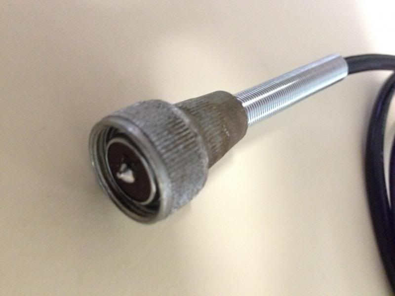
Nice to find a plug that is so easily serviceable, |
|
|
Return to top of page · Post #: 13 · Written at 5:01:14 PM on 17 January 2014.
|
|

|
Administrator
Location: Naremburn, NSW
Member since 15 November 2005 Member #: 1 Postcount: 7633 |
|
The plug will clean up with a 3M scourer laced with a potion of Ajax and ammonia. Elbow grease works every time. ‾‾‾‾‾‾‾‾‾‾‾‾‾‾‾‾‾‾‾‾‾‾‾‾‾‾‾‾‾‾‾‾‾‾‾‾‾‾‾‾‾‾‾‾‾‾‾‾‾‾‾‾‾‾‾‾‾‾‾‾‾‾‾‾‾‾‾‾ A valve a day keeps the transistor away... |
|
|
Return to top of page · Post #: 14 · Written at 10:03:06 PM on 17 January 2014.
|
|
|
|
Location: Somewhere, USA
Member since 22 October 2013 Member #: 1437 Postcount: 896 |
|
I will get pics up when it comes down to putting it back together. |
|
|
Return to top of page · Post #: 15 · Written at 10:13:30 PM on 17 January 2014.
|
|
|
|
Location: Somewhere, USA
Member since 22 October 2013 Member #: 1437 Postcount: 896 |
|
In case you missed that Brad Image Link it's another Jaycar spring |
|
|
You need to be a member to post comments on this forum.
|
|

Sign In
Vintage Radio and Television is proudly brought to you by an era where things were built with pride and made to last.
DISCLAIMER: Valve radios and televisions contain voltages that can deliver lethal shocks. You should not attempt to work on a valve radio or other electrical appliances unless you know exactly what you are doing and have gained some experience with electronics and working around high voltages. The owner, administrators and staff of Vintage Radio & Television will accept no liability for any damage, injury or loss of life that comes as a result of your use or mis-use of information on this website. Please read our Safety Warning before using this website.
WARNING: Under no circumstances should you ever apply power to a vintage radio, television or other electrical appliance you have acquired without first having it checked and serviced by an experienced person. Also, at no time should any appliance be connected to an electricity supply if the power cord is damaged. If in doubt, do not apply power.
Shintara - Keepin' It Real · VileSilencer - Maintain The Rage