
Workshops, Tools and Test Equipment
Forum home - Go back to Workshops, Tools and Test Equipment
|
Service jig or stand
|
|
|
« Back ·
1 ·
Next »
|
|
|
Return to top of page · Post #: 1 · Written at 9:09:54 AM on 12 June 2013.
|
|
|
|
Location: Canberra, ACT
Member since 23 August 2012 Member #: 1208 Postcount: 587 |
|
On the homepage of http://www.thebakeliteradio.com/ there is a historic illustration of a radio factory, where each chassis is fixed in a protective jig that enables it to be placed safely on a bench at any orientation as it goes through the factory. |
|
|
Return to top of page · Post #: 2 · Written at 12:04:14 PM on 12 June 2013.
|
|
|
|
Location: Blue Mountains, NSW
Member since 10 March 2013 Member #: 1312 Postcount: 401 |
|
Love the suit and tie under the dust jacket! |
|
|
Return to top of page · Post #: 3 · Written at 1:03:09 PM on 12 June 2013.
|
|

|
Location: Tamworth, NSW
Member since 6 April 2012 Member #: 1126 Postcount: 472 |
|
My jig is this. 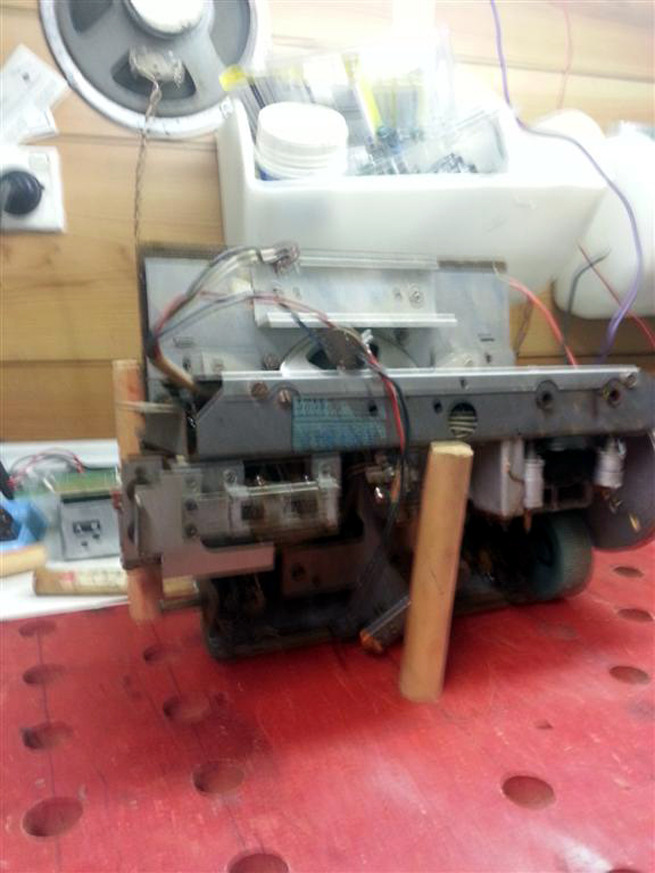 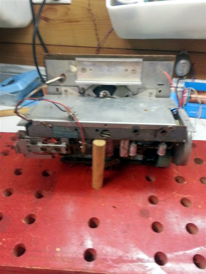 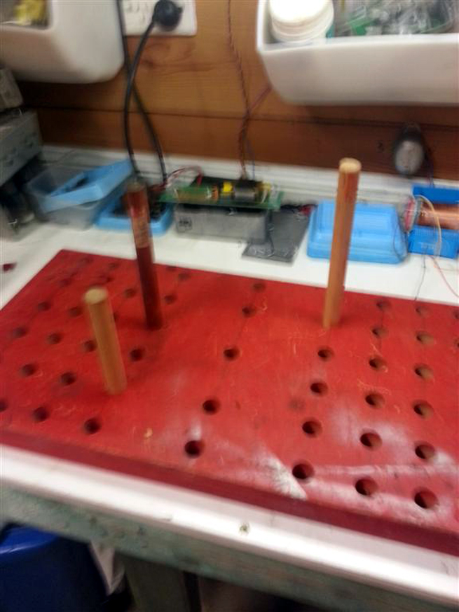 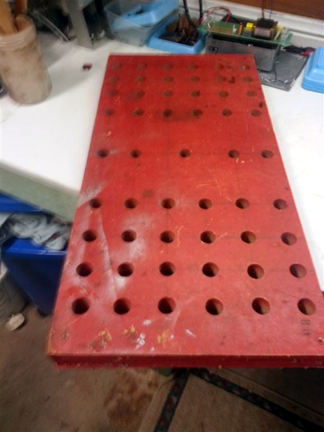 |
|
|
Return to top of page · Post #: 4 · Written at 1:22:56 PM on 12 June 2013.
|
|
|
|
Location: Blue Mountains, NSW
Member since 10 March 2013 Member #: 1312 Postcount: 401 |
|
Exactly the same as mine, far better description though. You can't have too many holes on the base board, I set the depth gauge on the drill press so mine don't go all the way through. I was limited by the reach of the press so couldn't get all the way to the centre leaving a section without holes. So far not a problem but a really tiny compact chassis could be difficult. I used 8mm dowels with 6mm rubber chair tips so the chassis can't slip, they're a tight fit but eventually go on. I could only find 6mm or 10mm tips. 6mm dowel is too small and 10 too big. To get the dowel to fit snugly in the base board I drilled the holes slightly undersize and cut small slots in the end of each dowel, same idea as some pots use to keep the knobs on. |
|
|
Return to top of page · Post #: 5 · Written at 6:59:18 PM on 12 June 2013.
|
|

|
Administrator
Location: Naremburn, NSW
Member since 15 November 2005 Member #: 1 Postcount: 7638 |
|
PVC conduit of a similar gauge to the metal frames pictured, whilst an ideal size, would not be strong enough for any bar the smallest radio chassis. ‾‾‾‾‾‾‾‾‾‾‾‾‾‾‾‾‾‾‾‾‾‾‾‾‾‾‾‾‾‾‾‾‾‾‾‾‾‾‾‾‾‾‾‾‾‾‾‾‾‾‾‾‾‾‾‾‾‾‾‾‾‾‾‾‾‾‾‾ A valve a day keeps the transistor away... |
|
|
Return to top of page · Post #: 6 · Written at 7:34:54 PM on 12 June 2013.
|
|
|
|
Location: Tamworth, NSW
Member since 6 April 2012 Member #: 1126 Postcount: 472 |
|
Ive just emailed Brad some pictures of my setup. |
|
|
Return to top of page · Post #: 7 · Written at 7:41:12 PM on 12 June 2013.
|
|
|
|
Administrator
Location: Naremburn, NSW
Member since 15 November 2005 Member #: 1 Postcount: 7638 |
|
Photos uploaded. ‾‾‾‾‾‾‾‾‾‾‾‾‾‾‾‾‾‾‾‾‾‾‾‾‾‾‾‾‾‾‾‾‾‾‾‾‾‾‾‾‾‾‾‾‾‾‾‾‾‾‾‾‾‾‾‾‾‾‾‾‾‾‾‾‾‾‾‾ A valve a day keeps the transistor away... |
|
|
Return to top of page · Post #: 8 · Written at 12:00:17 AM on 13 June 2013.
|
|

|
Location: Sydney, NSW
Member since 28 January 2011 Member #: 823 Postcount: 6960 |
|
I don't do enough radios to warrant one on my bench, but if I did I'd favour a rotisserie style that I've seen in old photos of repair shops back in the day. |
|
|
Return to top of page · Post #: 9 · Written at 4:04:51 PM on 13 June 2013.
|
|
|
|
Location: Canberra, ACT
Member since 23 August 2012 Member #: 1208 Postcount: 587 |
|
The dowel-farms look simple and effective, but I suppose need to be re-built if changing the position or angle of the chassis - say to solder something deep in a corner of the rats nest. |
|
|
Return to top of page · Post #: 10 · Written at 10:32:49 PM on 13 June 2013.
|
|
|
|
Location: Sydney, NSW
Member since 28 January 2011 Member #: 823 Postcount: 6960 |
|
Ha, I missed those links. Those units look pretty tidy and well-finished compared to what I have seen, but are the way to go I reckon. |
|
|
Return to top of page · Post #: 11 · Written at 5:25:16 PM on 14 June 2013.
|
|
|
|
Location: Canberra, ACT
Member since 23 August 2012 Member #: 1208 Postcount: 587 |
|
Well, I went ahead and built a servicing frame that turned out to be simpler than I expected. 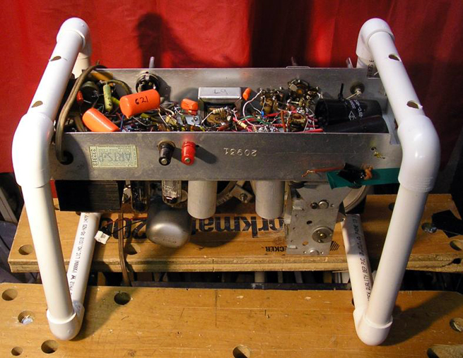 The two end hoops are made from 20mm rigid irrigation pipe sold in hardware places as "pressure pipe" for about $2.50 a metre. The 90degree corners are about $1.50 each. The hoops are fastened to the chassis with the original cabinet mounting bolts, accessed through the larger holes visible on the outer surface of the tubes. 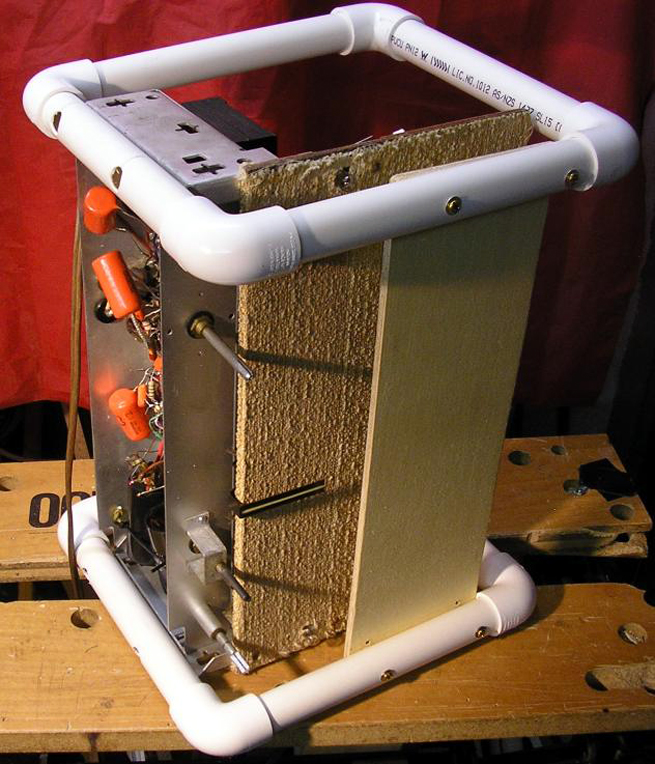 A piece of plywood bolted to both hoops across the front of the chassis provides all the lateral strength and stability you need, so the chassis can safely be stood on end if need be. 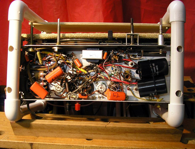 It is simple enough to prop the frame at an intermediate angle if desired. Here I am using the gap in my Workmate bench, plus a length of wood. The frame could be adjusted for different chassis types in different ways. You could make it large enough for your largest chassis, and have a range of holes in the base tubes for mounting, plus a range of bolt-holes in the plywood lateral piece for different widths. So far, I have found that the hoops stay together purely by the friction in the corner pieces, like tinker-toy, even if I lift the assembly from the top with the chassis in it. So it would be simple to keep a range of tube lengths to reconfigure the hoop size. For more security, the corners could be fixed to the tubes with push-through pins. Originally, I planned to glue those corners, but now I plan to leave them as they are. This will be more convenient for adjustment and also for storage. When not in use - take off the plywood lateral and the frame will store flat in three pieces. Maven |
|
|
Return to top of page · Post #: 12 · Written at 9:27:39 AM on 26 June 2013.
|
|

|
Location: Wangaratta, VIC
Member since 21 February 2009 Member #: 438 Postcount: 5730 |
|
|
|
|
Return to top of page · Post #: 13 · Written at 9:30:41 AM on 26 June 2013.
|
|
|
|
Location: Wangaratta, VIC
Member since 21 February 2009 Member #: 438 Postcount: 5730 |
|
Some HMV sets like Nippers & some Grams. show a lot of forward thinking. |
|
|
Return to top of page · Post #: 14 · Written at 2:13:30 PM on 26 June 2013.
|
|
|
|
Location: Sydney, NSW
Member since 28 January 2011 Member #: 823 Postcount: 6960 |
|
Nice work, Maven! |
|
|
Return to top of page · Post #: 15 · Written at 12:20:52 PM on 28 June 2013.
|
|
|
|
Location: Canberra, ACT
Member since 23 August 2012 Member #: 1208 Postcount: 587 |
|
I've been using this for a couple of weeks now, and it's a big improvement on the bench-balancing I was doing before. |
|
|
« Back ·
1 ·
Next »
|
|
|
You need to be a member to post comments on this forum.
|
|
 and a router.
 cox.net
Sign In
Vintage Radio and Television is proudly brought to you by an era where things were built with pride and made to last.
DISCLAIMER: Valve radios and televisions contain voltages that can deliver lethal shocks. You should not attempt to work on a valve radio or other electrical appliances unless you know exactly what you are doing and have gained some experience with electronics and working around high voltages. The owner, administrators and staff of Vintage Radio & Television will accept no liability for any damage, injury or loss of life that comes as a result of your use or mis-use of information on this website. Please read our Safety Warning before using this website.
WARNING: Under no circumstances should you ever apply power to a vintage radio, television or other electrical appliance you have acquired without first having it checked and serviced by an experienced person. Also, at no time should any appliance be connected to an electricity supply if the power cord is damaged. If in doubt, do not apply power.
Shintara - Keepin' It Real · VileSilencer - Maintain The Rage