
Workshops, Tools and Test Equipment
Forum home - Go back to Workshops, Tools and Test Equipment
|
RTV&H R/C bridge
|
|
|
« Back ·
1 ·
Next »
|
|
|
Return to top of page · Post #: 1 · Written at 10:11:17 AM on 8 February 2019.
|
|
|
|
Location: Broken Hill, NSW
Member since 4 October 2018 Member #: 2302 Postcount: 6 |
|
Hi, |
|
|
Return to top of page · Post #: 2 · Written at 10:20:17 AM on 8 February 2019.
|
|
|
|
Location: Toongabbie, NSW
Member since 19 November 2015 Member #: 1828 Postcount: 1404 |
|
Silicon chip market the CD with all the RHTV magazines scanned onto it. |
|
|
Return to top of page · Post #: 3 · Written at 2:20:18 PM on 8 February 2019.
|
|
|
|
Location: Cameron Park, NSW
Member since 5 November 2010 Member #: 770 Postcount: 426 |
|
The September 1958 issue describes the updated R/C bridge, which includes the gain control and a value / tolerance switch. However it uses a 6U8 triode pentode, but I can see that a twin triode could do the same job. 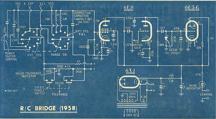 |
|
|
Return to top of page · Post #: 4 · Written at 3:05:10 PM on 8 February 2019.
|
|
|
|
Location: Broken Hill, NSW
Member since 4 October 2018 Member #: 2302 Postcount: 6 |
|
Found a copy of the 1958 issue. Circuit diagram almost spot on matches what I traced out in mine aside from the different valve being used and a few minor modifications. Thanks! |
|
|
Return to top of page · Post #: 5 · Written at 4:14:57 PM on 8 February 2019.
|
|

|
Location: Sydney, NSW
Member since 28 January 2011 Member #: 823 Postcount: 6942 |
|
The December 1954 article (6X4, 6N8, 6U5) says it's a "new dress" for the original described in December 1948 therein called the Standard RC Bridge (6X5, 6B6, 8U5/6G5). |
|
|
Return to top of page · Post #: 6 · Written at 6:53:50 PM on 12 February 2019.
|
|

|
Administrator
Location: Naremburn, NSW
Member since 15 November 2005 Member #: 1 Postcount: 7614 |
|
Photo uploaded to Post 3. ‾‾‾‾‾‾‾‾‾‾‾‾‾‾‾‾‾‾‾‾‾‾‾‾‾‾‾‾‾‾‾‾‾‾‾‾‾‾‾‾‾‾‾‾‾‾‾‾‾‾‾‾‾‾‾‾‾‾‾‾‾‾‾‾‾‾‾‾ A valve a day keeps the transistor away... |
|
|
Return to top of page · Post #: 7 · Written at 6:00:54 AM on 15 February 2019.
|
|

|
Location: Wangaratta, VIC
Member since 21 February 2009 Member #: 438 Postcount: 5699 |
|
The globe would actually act as a "Hot wire" Barretter, It may have also been an attempt at a cheap regulator and surge limiter for the 6X5. AWA often put a 1/2 watt resistor in series with the plates of 6X5. It works by changing the self bias as all cathode current goes through it. |
|
|
Return to top of page · Post #: 8 · Written at 9:41:25 AM on 31 March 2019.
|
|
|
|
Location: Melbourne, VIC
Member since 11 July 2012 Member #: 1179 Postcount: 65 |
|
The small light bulb would be passing the 100Hz peaky current pulses charging the 8μF cap input filter. Given the 225V secondary and its effective series resistance, and 6X4 anode resistance, I doubt the bulb filament resistance would have noticeably changed the droop dominated by the secondary winding and anode resistances. I would think its ability to act as a poor mans fuse, and possibly as a faultfinding indicator would be its main purposes. |
|
|
Return to top of page · Post #: 9 · Written at 11:07:13 AM on 27 April 2019.
|
|
|
|
Location: Broken Hill, NSW
Member since 4 October 2018 Member #: 2302 Postcount: 6 |
|
Thanks everyone for the comments and ideas. |
|
|
« Back ·
1 ·
Next »
|
|
|
You need to be a member to post comments on this forum.
|
|
Sign In
Vintage Radio and Television is proudly brought to you by an era where things were built with pride and made to last.
DISCLAIMER: Valve radios and televisions contain voltages that can deliver lethal shocks. You should not attempt to work on a valve radio or other electrical appliances unless you know exactly what you are doing and have gained some experience with electronics and working around high voltages. The owner, administrators and staff of Vintage Radio & Television will accept no liability for any damage, injury or loss of life that comes as a result of your use or mis-use of information on this website. Please read our Safety Warning before using this website.
WARNING: Under no circumstances should you ever apply power to a vintage radio, television or other electrical appliance you have acquired without first having it checked and serviced by an experienced person. Also, at no time should any appliance be connected to an electricity supply if the power cord is damaged. If in doubt, do not apply power.
Shintara - Keepin' It Real · VileSilencer - Maintain The Rage