
Workshops, Tools and Test Equipment
Forum home - Go back to Workshops, Tools and Test Equipment
|
Klein & Hummel FS-4-A circuit wanted.
|
|
|
« Back ·
1 ·
Next »
|
|
|
Return to top of page · Post #: 1 · Written at 9:32:45 AM on 15 June 2017.
|
|

|
Location: Beechmont, QLD
Member since 10 April 2009 Member #: 465 Postcount: 109 |
|
Hello all. 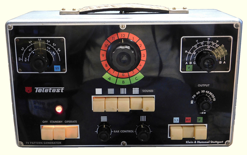 |
|
|
Return to top of page · Post #: 2 · Written at 9:42:50 AM on 15 June 2017.
|
|
|
|
Location: Beechmont, QLD
Member since 10 April 2009 Member #: 465 Postcount: 109 |
|
I forgot to add that Radiomuseum.org has a circuit for an FS-4, but this is not the same, using different valves and circuitry. |
|
|
Return to top of page · Post #: 3 · Written at 11:36:02 AM on 15 June 2017.
|
|
|
|
Location: Belrose, NSW
Member since 31 December 2015 Member #: 1844 Postcount: 2713 |
|
You'd be lucky to find a circuit for that! |
|
|
Return to top of page · Post #: 4 · Written at 8:15:11 PM on 15 June 2017.
|
|
|
|
Location: Beechmont, QLD
Member since 10 April 2009 Member #: 465 Postcount: 109 |
|
Thanks Ian for your offer. I know there is at least one component missing because a screen grid is connected to a bypass capacitor but nothing else. Its quite complicated, 12 valves, almost all double types. Trouble is, someone had been there before me and may have made mistakes. Another trouble is that the thing is extremely difficult to work on. I have taken photos but the missing component was not there before I started. I'd like to see if I can get the circuit before I strip it down again. I've added the model to Radiomuseum.org and I'll see if I can get one there. Thanks anyway. Cheers. |
|
|
Return to top of page · Post #: 5 · Written at 9:05:23 PM on 16 June 2017.
|
|

|
Administrator
Location: Naremburn, NSW
Member since 15 November 2005 Member #: 1 Postcount: 7638 |
|
Photo uploaded. ‾‾‾‾‾‾‾‾‾‾‾‾‾‾‾‾‾‾‾‾‾‾‾‾‾‾‾‾‾‾‾‾‾‾‾‾‾‾‾‾‾‾‾‾‾‾‾‾‾‾‾‾‾‾‾‾‾‾‾‾‾‾‾‾‾‾‾‾ A valve a day keeps the transistor away... |
|
|
Return to top of page · Post #: 6 · Written at 9:45:27 PM on 16 June 2017.
|
|

|
Location: Sydney, NSW
Member since 28 January 2011 Member #: 823 Postcount: 6960 |
|
Nice looking piece of gear that. |
|
|
Return to top of page · Post #: 7 · Written at 10:25:00 AM on 28 June 2017.
|
|
|
|
Location: Beechmont, QLD
Member since 10 April 2009 Member #: 465 Postcount: 109 |
|
Hi All. |
|
|
Return to top of page · Post #: 8 · Written at 11:45:05 AM on 28 June 2017.
|
|
|
|
Location: Belrose, NSW
Member since 31 December 2015 Member #: 1844 Postcount: 2713 |
|
If the circuit is locking an oscillator to the mains, the phase will be affected by ripple control signals ("Zellweger") imposed on the mains by power suppliers for remote control of things like water heaters. Probably not around when and where this was designed. Not a great deal you can do except don't sync it to the mains, that might be the best solution. |
|
|
Return to top of page · Post #: 9 · Written at 9:42:44 AM on 29 June 2017.
|
|
|
|
Location: Beechmont, QLD
Member since 10 April 2009 Member #: 465 Postcount: 109 |
|
Thanks Ian. Yes I thought of that, but it happens when these control signals are absent. I've looked carefully at the oscillator signal and the mains input signal at the same time on a dual channel CRO and can't see anything on the mains waveform (just the 6.3 volt heater supply line) that can account for the jitter. 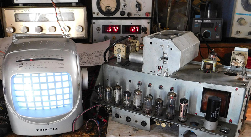 |
|
|
Return to top of page · Post #: 10 · Written at 10:00:08 AM on 29 June 2017.
|
|
|
|
Location: Toongabbie, NSW
Member since 19 November 2015 Member #: 1828 Postcount: 1413 |
|
Sirwin, just a thought adding to Ian's reasoning. |
|
|
Return to top of page · Post #: 11 · Written at 12:07:07 PM on 29 June 2017.
|
|
|
|
Location: Belrose, NSW
Member since 31 December 2015 Member #: 1844 Postcount: 2713 |
|
Yes, Fred, you are right. That kind of filtering is actually done in software in dimmers, where it's VERY important to get a stable trigger point or your lights fade up and down randomly. |
|
|
Return to top of page · Post #: 12 · Written at 4:59:47 AM on 30 June 2017.
|
|
|
|
Administrator
Location: Naremburn, NSW
Member since 15 November 2005 Member #: 1 Postcount: 7638 |
|
Photo uploaded to Post 9. ‾‾‾‾‾‾‾‾‾‾‾‾‾‾‾‾‾‾‾‾‾‾‾‾‾‾‾‾‾‾‾‾‾‾‾‾‾‾‾‾‾‾‾‾‾‾‾‾‾‾‾‾‾‾‾‾‾‾‾‾‾‾‾‾‾‾‾‾ A valve a day keeps the transistor away... |
|
|
Return to top of page · Post #: 13 · Written at 2:53:02 PM on 8 July 2017.
|
|
|
|
Location: Beechmont, QLD
Member since 10 April 2009 Member #: 465 Postcount: 109 |
|
Hi Fred & Ian. Yes, I'll look into that. Certainly my mains waveform is noticeably distorted, not just from "electronic" power supplies but also no doubt from the fact that most of my neighbours have solar photovoltaic systems. I will try replacing the mains signal with one from my audio generator, to see if that makes a difference. |
|
|
Return to top of page · Post #: 14 · Written at 3:17:00 PM on 8 July 2017.
|
|
|
|
Location: Belrose, NSW
Member since 31 December 2015 Member #: 1844 Postcount: 2713 |
|
Hi Stuart |
|
|
« Back ·
1 ·
Next »
|
|
|
You need to be a member to post comments on this forum.
|
|
Sign In
Vintage Radio and Television is proudly brought to you by an era where things were built with pride and made to last.
DISCLAIMER: Valve radios and televisions contain voltages that can deliver lethal shocks. You should not attempt to work on a valve radio or other electrical appliances unless you know exactly what you are doing and have gained some experience with electronics and working around high voltages. The owner, administrators and staff of Vintage Radio & Television will accept no liability for any damage, injury or loss of life that comes as a result of your use or mis-use of information on this website. Please read our Safety Warning before using this website.
WARNING: Under no circumstances should you ever apply power to a vintage radio, television or other electrical appliance you have acquired without first having it checked and serviced by an experienced person. Also, at no time should any appliance be connected to an electricity supply if the power cord is damaged. If in doubt, do not apply power.
Shintara - Keepin' It Real · VileSilencer - Maintain The Rage