
Workshops, Tools and Test Equipment
Forum home - Go back to Workshops, Tools and Test Equipment
|
Short Circuit Detector and disaster prevention.
|
|
|
« Back ·
1 ·
Next »
|
|
|
Return to top of page · Post #: 1 · Written at 3:33:54 PM on 29 January 2016.
|
|

|
Location: Latham, ACT
Member since 21 February 2015 Member #: 1705 Postcount: 2227 |
|
Wow guys this very simple device which I made up according to directions from my technician is briliant for detecting short circuits and preventing disasters such as the meltdown I had with the Hotpoint Radio in tech advice. 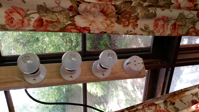 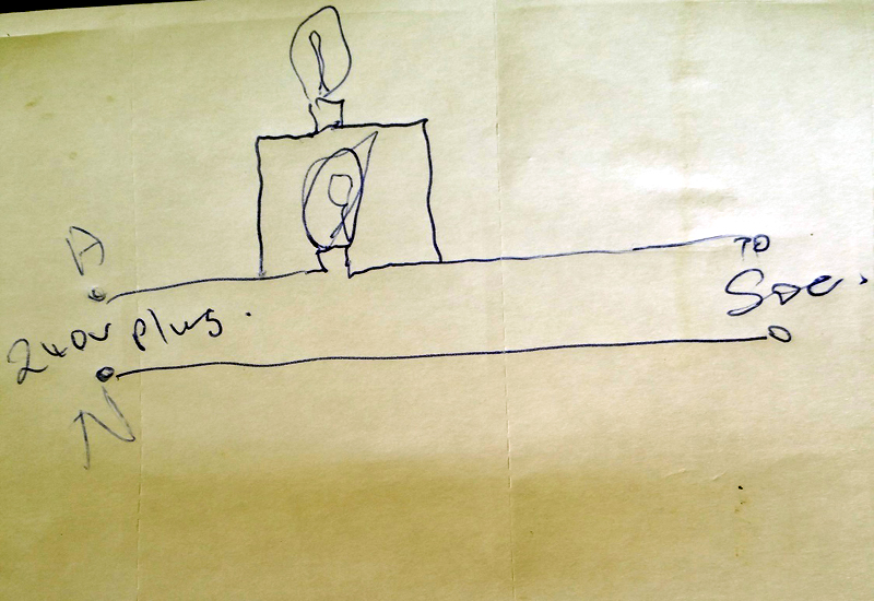 |
|
|
Return to top of page · Post #: 2 · Written at 11:12:08 PM on 29 January 2016.
|
|

|
Location: Sydney, NSW
Member since 28 January 2011 Member #: 823 Postcount: 6942 |
|
Known mostly as a dim bulb tester -- the bulb is goes dim if there is no short and remains bright if there is a short. |
|
|
Return to top of page · Post #: 3 · Written at 10:22:22 AM on 30 January 2016.
|
|
|
|
Location: Latham, ACT
Member since 21 February 2015 Member #: 1705 Postcount: 2227 |
|
No that is actually the correct wiring diagram. The fellow who drew it up actually cut his teeth on valve radios and that is the diagram I used to build it. You only need two bulbs but I opted for three. As I said if your radio is ok then no bulbs light up ( not dim ) and if there is a short then they are bright. |
|
|
Return to top of page · Post #: 4 · Written at 5:33:56 PM on 30 January 2016.
|
|
|
|
Location: Sydney, NSW
Member since 28 January 2011 Member #: 823 Postcount: 6942 |
|
Depends on inrush current of the set/equipment under test. This will vary, depending on design of the load. Some will draw significant current briefly, and then settle down to the rated wattage once valves are operating and capacitors are charged up. |
|
|
Return to top of page · Post #: 5 · Written at 8:05:52 PM on 30 January 2016.
|
|
|
|
Location: Latham, ACT
Member since 21 February 2015 Member #: 1705 Postcount: 2227 |
|
Ok I have a question . He has this operating with a isolation transformer and a variac . Does it Matter which one is in the power point first or can it be any which way. I have not asked him yet but will. |
|
|
Return to top of page · Post #: 6 · Written at 8:16:31 PM on 30 January 2016.
|
|
|
|
Location: Sydney, NSW
Member since 28 January 2011 Member #: 823 Postcount: 6942 |
|
The role of an isolation transformer is to remove the link to earth, which exists at the meter board where usually the neutral link is physically joined to the earth rod. The transformer therefore makes the mains on the secondary side "float" above earth so that anybody connected to earth does not complete a 240 volt circuit through their body. |
|
|
Return to top of page · Post #: 7 · Written at 8:46:54 PM on 30 January 2016.
|
|
|
|
Location: Latham, ACT
Member since 21 February 2015 Member #: 1705 Postcount: 2227 |
|
So I am guessing that it should be isolating transformer then the Dim Bulb Tester and then the Variac because I'm assuming the Bulbs may not like the input being varied. Just putting the queery out there. |
|
|
Return to top of page · Post #: 8 · Written at 8:56:05 PM on 30 January 2016.
|
|
|
|
Location: Sydney, NSW
Member since 28 January 2011 Member #: 823 Postcount: 6942 |
|
Voltage-wise, bulbs don't mind anything as long as it's not above their rated voltage. You can bring a bulb from off to full on via a variac, just like a domestic light dimmer (except that they use triacs). |
|
|
Return to top of page · Post #: 9 · Written at 9:38:53 PM on 30 January 2016.
|
|

|
Administrator
Location: Naremburn, NSW
Member since 15 November 2005 Member #: 1 Postcount: 7614 |
|
Standard light globes are a purely resistive load. You can dim them pretty much any way you want. Baretters, that are used in many Australian AC/DC sets are pretty much a 60-75 watt light globe and were a cheap and reasonably reliable way of limiting current flow. ‾‾‾‾‾‾‾‾‾‾‾‾‾‾‾‾‾‾‾‾‾‾‾‾‾‾‾‾‾‾‾‾‾‾‾‾‾‾‾‾‾‾‾‾‾‾‾‾‾‾‾‾‾‾‾‾‾‾‾‾‾‾‾‾‾‾‾‾ A valve a day keeps the transistor away... |
|
|
Return to top of page · Post #: 10 · Written at 12:10:55 AM on 31 January 2016.
|
|
|
|
Location: Latham, ACT
Member since 21 February 2015 Member #: 1705 Postcount: 2227 |
|
Ah of cause I did not think of the light dimmer situation now that makes things a little clearer. |
|
|
Return to top of page · Post #: 11 · Written at 2:39:00 AM on 16 February 2016.
|
|
|
|
Location: Somewhere, USA
Member since 22 October 2013 Member #: 1437 Postcount: 896 |
|
The light bulb is an old trick, the poor man’s variac. |
|
|
« Back ·
1 ·
Next »
|
|
|
You need to be a member to post comments on this forum.
|
|
Sign In
Vintage Radio and Television is proudly brought to you by an era where things were built with pride and made to last.
DISCLAIMER: Valve radios and televisions contain voltages that can deliver lethal shocks. You should not attempt to work on a valve radio or other electrical appliances unless you know exactly what you are doing and have gained some experience with electronics and working around high voltages. The owner, administrators and staff of Vintage Radio & Television will accept no liability for any damage, injury or loss of life that comes as a result of your use or mis-use of information on this website. Please read our Safety Warning before using this website.
WARNING: Under no circumstances should you ever apply power to a vintage radio, television or other electrical appliance you have acquired without first having it checked and serviced by an experienced person. Also, at no time should any appliance be connected to an electricity supply if the power cord is damaged. If in doubt, do not apply power.
Shintara - Keepin' It Real · VileSilencer - Maintain The Rage