
Historical Features
Forum home - Go back to Historical Features
|
Autovox valve car radio
|
|
|
Return to top of page · Post #: 16 · Written at 4:20:37 PM on 4 March 2023.
|
|
|
|
Location: Toongabbie, NSW
Member since 19 November 2015 Member #: 1828 Postcount: 1253 |
|
Rob, has a point. |
|
|
Return to top of page · Post #: 17 · Written at 5:13:44 PM on 5 March 2023.
|
|
|
|
Location: Nowra, NSW
Member since 19 February 2023 Member #: 2539 Postcount: 12 |
|
Confusion reigns. Some of the component labels on the schematic (thanks GTC) are confusing (to me). For example, some capacitor labels used are 250, 0.1, or 8.(full stop), while some resistors are labelled 0.27, or. 1. or. 47.k(full stop). |
|
|
Return to top of page · Post #: 18 · Written at 5:14:37 PM on 5 March 2023.
|
|
|
|
Location: Nowra, NSW
Member since 19 February 2023 Member #: 2539 Postcount: 12 |
|
...... |
|
|
Return to top of page · Post #: 19 · Written at 5:23:55 PM on 5 March 2023.
|
|
|
|
Location: Nowra, NSW
Member since 19 February 2023 Member #: 2539 Postcount: 12 |
|
...... |
|
|
Return to top of page · Post #: 20 · Written at 8:00:33 PM on 5 March 2023.
|
|
|
|
Location: Linton, VIC
Member since 30 December 2016 Member #: 2028 Postcount: 468 |
|
Yep, you are in a pickle, the schematic is 'screwy', but we can work through this. |
|
|
Return to top of page · Post #: 21 · Written at 8:05:01 PM on 5 March 2023.
|
|
|
|
Location: Toongabbie, NSW
Member since 19 November 2015 Member #: 1828 Postcount: 1253 |
|
Wow! |
|
|
Return to top of page · Post #: 22 · Written at 6:26:21 PM on 6 March 2023.
|
|
|
|
Location: Nowra, NSW
Member since 19 February 2023 Member #: 2539 Postcount: 12 |
|
Almost there?? Looking at other circuits, and using some logic, I think this is the translation for components. |
|
|
Return to top of page · Post #: 23 · Written at 7:56:26 PM on 6 March 2023.
|
|
|
|
Location: Linton, VIC
Member since 30 December 2016 Member #: 2028 Postcount: 468 |
|
Yes, it is on a HT rail, and forms a pi filter with the 30μF electro. Can you see it? An inspection will soon reveal if it's an electro cap or not. |
|
|
Return to top of page · Post #: 24 · Written at 8:25:22 PM on 6 March 2023.
|
|
|
|
Location: Toongabbie, NSW
Member since 19 November 2015 Member #: 1828 Postcount: 1253 |
|
By George, I think he has got it!!! |
|
|
Return to top of page · Post #: 25 · Written at 9:22:16 AM on 7 March 2023.
|
|
|
|
Location: Nowra, NSW
Member since 19 February 2023 Member #: 2539 Postcount: 12 |
|
Thanks guys. Now for some careful progress. |
|
|
Return to top of page · Post #: 26 · Written at 1:49:37 PM on 7 March 2023.
|
|
|
|
Location: Nowra, NSW
Member since 19 February 2023 Member #: 2539 Postcount: 12 |
|
Another of the seemingly endless queries. Where to buy capacitors in the range 50 - 425 pF (as shown on schematic) in Australia? Assume they would be high voltage (up to 600v), and for use on AC? |
|
|
Return to top of page · Post #: 27 · Written at 10:53:37 PM on 7 March 2023.
|
|
|
|
Location: Belrose, NSW
Member since 31 December 2015 Member #: 1844 Postcount: 2375 |
|
Au.element14.com, for one. |
|
|
Return to top of page · Post #: 28 · Written at 7:32:15 AM on 8 March 2023.
|
|

|
Location: Latham, ACT
Member since 21 February 2015 Member #: 1705 Postcount: 2158 |
|
You might want to contact Kevin Chant and purchase one of his solid state vibrators. Much more reliable. |
|
|
Return to top of page · Post #: 29 · Written at 7:19:34 PM on 9 March 2023.
|
|
|
|
Location: Nowra, NSW
Member since 19 February 2023 Member #: 2539 Postcount: 12 |
|
I have sent 2 pics to Brad. One pic is view of the underside of the chassis - other pic is view of the station pointer mechanism. 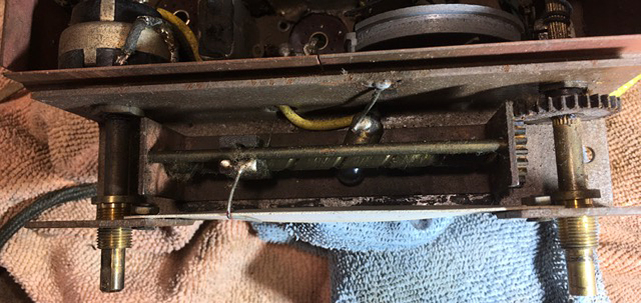 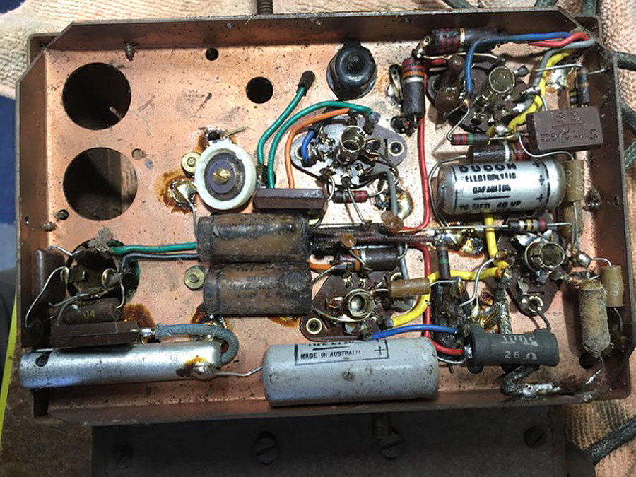 |
|
|
Return to top of page · Post #: 30 · Written at 7:26:04 PM on 9 March 2023.
|
|
|
|
Location: Belrose, NSW
Member since 31 December 2015 Member #: 1844 Postcount: 2375 |
|
You are talking about a museum grade restoration where you melt the insides out of the paper caps and put new caps inside the sleeves. Seal the ends with hotmelt and you have a new cap that looks original. |
|
|
You need to be a member to post comments on this forum.
|
|
Sign In
Vintage Radio and Television is proudly brought to you by an era where things were built with pride and made to last.
DISCLAIMER: Valve radios and televisions contain voltages that can deliver lethal shocks. You should not attempt to work on a valve radio or other electrical appliances unless you know exactly what you are doing and have gained some experience with electronics and working around high voltages. The owner, administrators and staff of Vintage Radio & Television will accept no liability for any damage, injury or loss of life that comes as a result of your use or mis-use of information on this website. Please read our Safety Warning before using this website.
WARNING: Under no circumstances should you ever apply power to a vintage radio, television or other electrical appliance you have acquired without first having it checked and serviced by an experienced person. Also, at no time should any appliance be connected to an electricity supply if the power cord is damaged. If in doubt, do not apply power.
Shintara - Keepin' It Real · VileSilencer - Maintain The Rage