
General Discussion
Forum home - Go back to General discussion
|
1934 EMMCO Jewel Console
|
|
|
Return to top of page · Post #: 46 · Written at 10:58:35 AM on 15 November 2016.
|
|

|
Location: Wangaratta, VIC
Member since 21 February 2009 Member #: 438 Postcount: 5257 |
|
Circuit emailed: 10k would likely go to antenna coil and 200 Ohm to the cathodes. Refer circuit. 110 Ohm is not a common value to me. |
|
|
Return to top of page · Post #: 47 · Written at 6:21:35 PM on 15 November 2016.
|
|

|
Location: Latham, ACT
Member since 21 February 2015 Member #: 1705 Postcount: 2158 |
|
I didn't get the email. I checked trash and spam as well but no. Strangely enough since that photo was taken the orange dot has disappeared and the resistor seems to have burnt some more though I smelt nothing burning. |
|
|
Return to top of page · Post #: 48 · Written at 9:20:01 PM on 15 November 2016.
|
|

|
Administrator
Location: Naremburn, NSW
Member since 15 November 2005 Member #: 1 Postcount: 7307 |
|
File uploaded to Post 46. ‾‾‾‾‾‾‾‾‾‾‾‾‾‾‾‾‾‾‾‾‾‾‾‾‾‾‾‾‾‾‾‾‾‾‾‾‾‾‾‾‾‾‾‾‾‾‾‾‾‾‾‾‾‾‾‾‾‾‾‾‾‾‾‾‾‾‾‾ A valve a day keeps the transistor away... |
|
|
Return to top of page · Post #: 49 · Written at 10:34:33 PM on 15 November 2016.
|
|
|
|
Location: Wangaratta, VIC
Member since 21 February 2009 Member #: 438 Postcount: 5257 |
|
Measure the voltage across that resistor. Apart from Rk burning via a heater cathode short; In that bias system it is one great big voltage divider and the potentiometer working as a volume, quite often places more positive on the cathodes from B+ by adding resistance to the dividers earth leg. |
|
|
Return to top of page · Post #: 50 · Written at 10:39:05 PM on 15 November 2016.
|
|
|
|
Location: Latham, ACT
Member since 21 February 2015 Member #: 1705 Postcount: 2158 |
|
Received with thanks. |
|
|
Return to top of page · Post #: 51 · Written at 7:19:10 PM on 16 November 2016.
|
|
|
|
Location: Latham, ACT
Member since 21 February 2015 Member #: 1705 Postcount: 2158 |
|
Hi Marcc . In my research over the last few weeks with the HRSA schematic service they came up with a schematic from Weldon as the closest to my EMMCO. I was lucky enough to purchase AORSM no 2 ( 1938 ) I looked up Weldon and found that their 3/38 has exactly the same components as my EMMCO down to the 10K pots. I am learning how to read these schematics and just wondering if you might be able to have a look and if there is any advice you may be able to think of for me. . The EMMCO is a Superhet as is the Weldon Your advice has been of great help to me . |
|
|
Return to top of page · Post #: 52 · Written at 8:45:11 PM on 21 November 2016.
|
|
|
|
Location: Latham, ACT
Member since 21 February 2015 Member #: 1705 Postcount: 2158 |
|
Well Guys I was quite happy with the progress of this unit knowing that I had not changed the circuit ( put wires in the wrong place ) . As I had no way of testing the valves I thought the best thing was to take it to my tech and ask him to do that. He did a few quick checks and found that one of the pots that had been given to me was OC. As he changed the pot he uttered famous last words " I doubt if this will work tonight as I think it may have numerous problems " then he powered it up and hey presto it sprung to life after 50 years dormant . It was actually running well under 240 volts as it was sitting on about 160 on the variac. I Had done a recap but no resistors had been changed . That will happen though He has kept it and is doing a final tune for me and I will be putting it all back together yaay. |
|
|
Return to top of page · Post #: 53 · Written at 10:45:47 PM on 21 November 2016.
|
|
|
|
Location: Wangaratta, VIC
Member since 21 February 2009 Member #: 438 Postcount: 5257 |
|
I would have liked to have tested the resistors first before alignment, I normally do that as I change the caps as they can bring down a set and rework always comes with risk. The least amount of work you do the lesser is the risk of breaking something. |
|
|
Return to top of page · Post #: 54 · Written at 11:20:52 PM on 21 November 2016.
|
|
|
|
Location: Latham, ACT
Member since 21 February 2015 Member #: 1705 Postcount: 2158 |
|
Yeah he is a old radio Guy . Yeah he cut his teeth on valves . I am a very lucky guy to know him. He lives just around the corner from me and has always said to me that I am welcome to come around at any time. He honestly was not confident that it was going to work straight up but what a pleasant surprise. |
|
|
Return to top of page · Post #: 55 · Written at 2:30:36 AM on 3 December 2016.
|
|
|
|
Location: Latham, ACT
Member since 21 February 2015 Member #: 1705 Postcount: 2158 |
|
I am just about to finish this old Girl. I thought I might send some pics of the chassis clean up. I achieved this by just using white vinegar, a toothbrush , some wet and dry and a little metal polish. Not real bad. 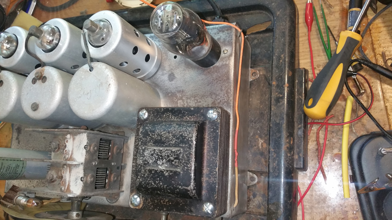 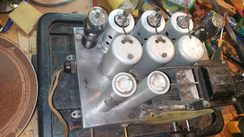 |
|
|
Return to top of page · Post #: 56 · Written at 10:35:30 AM on 5 December 2016.
|
|
|
|
Location: Latham, ACT
Member since 21 February 2015 Member #: 1705 Postcount: 2158 |
|
Well guys here is the finished article. The woodwork is original untouched (except beeswax) 1934 as it came out of the factory. 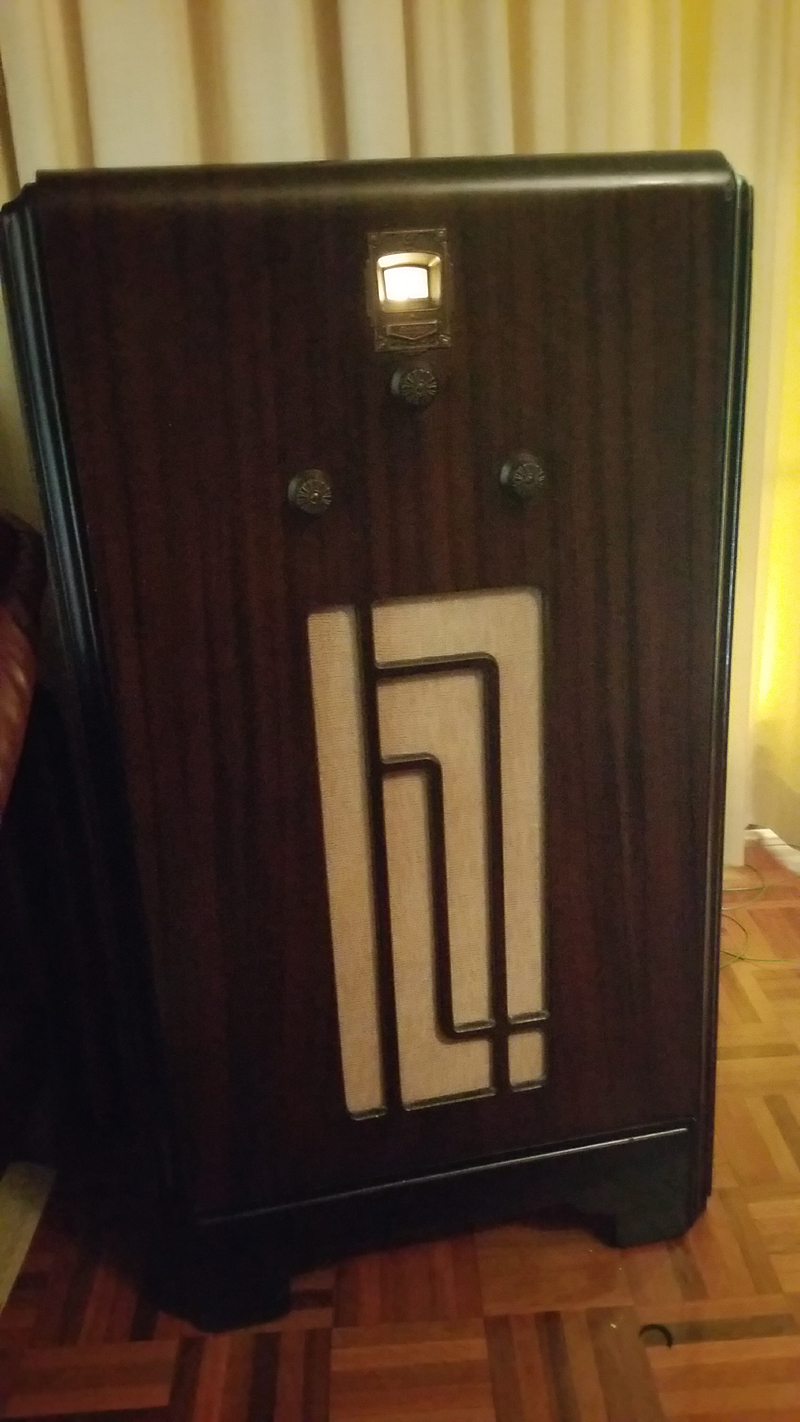 With the risk of getting a smack on the wrist it turned out that all the original resistors tested ok and I did not really see the need to change them (nor did the tech) this old girl has a beautiful tone to which I am quite astounded. |
|
|
Return to top of page · Post #: 57 · Written at 5:22:49 PM on 6 December 2016.
|
|
|
|
Administrator
Location: Naremburn, NSW
Member since 15 November 2005 Member #: 1 Postcount: 7307 |
|
I think that resistors can simply just be replaced when they fall out of tolerance. I rarely replace any and when I do it is a last resort. Capacitors are a different story though - electros and papers and the infamous AWA blackies are just replaced, no matter what. ‾‾‾‾‾‾‾‾‾‾‾‾‾‾‾‾‾‾‾‾‾‾‾‾‾‾‾‾‾‾‾‾‾‾‾‾‾‾‾‾‾‾‾‾‾‾‾‾‾‾‾‾‾‾‾‾‾‾‾‾‾‾‾‾‾‾‾‾ A valve a day keeps the transistor away... |
|
|
Return to top of page · Post #: 58 · Written at 9:28:35 PM on 6 December 2016.
|
|
|
|
Location: Latham, ACT
Member since 21 February 2015 Member #: 1705 Postcount: 2158 |
|
I am guessing that resistors don't go off with age but rather with use or abuse. I get the impression the radio didn't get much use but did get a bit of abuse. |
|
|
Return to top of page · Post #: 59 · Written at 10:01:24 PM on 6 December 2016.
|
|

|
Location: Tamworth, NSW
Member since 6 April 2012 Member #: 1126 Postcount: 466 |
|
Ive lost count of how many 1meg resistors Ive replaced over the years. Its easier to check them while caps are unsoldered. |
|
|
Return to top of page · Post #: 60 · Written at 11:41:08 PM on 6 December 2016.
|
|
|
|
Location: Wangaratta, VIC
Member since 21 February 2009 Member #: 438 Postcount: 5257 |
|
There is a pattern and I keep stocks as I repair. The greatest stock I carry is 47k & 470k, 100k and 5-10 of everything else other than some common WW and 2 & 3 Watt. I mainly stock 1 Watt en mass. |
|
|
You need to be a member to post comments on this forum.
|
|

Sign In
Vintage Radio and Television is proudly brought to you by an era where things were built with pride and made to last.
DISCLAIMER: Valve radios and televisions contain voltages that can deliver lethal shocks. You should not attempt to work on a valve radio or other electrical appliances unless you know exactly what you are doing and have gained some experience with electronics and working around high voltages. The owner, administrators and staff of Vintage Radio & Television will accept no liability for any damage, injury or loss of life that comes as a result of your use or mis-use of information on this website. Please read our Safety Warning before using this website.
WARNING: Under no circumstances should you ever apply power to a vintage radio, television or other electrical appliance you have acquired without first having it checked and serviced by an experienced person. Also, at no time should any appliance be connected to an electricity supply if the power cord is damaged. If in doubt, do not apply power.
Shintara - Keepin' It Real · VileSilencer - Maintain The Rage