
General Discussion
Forum home - Go back to General discussion
|
STERLING radio
|
|
|
Return to top of page · Post #: 1 · Written at 12:44:15 AM on 4 November 2015.
|
|
|
|
Location: Perth, WA
Member since 2 November 2015 Member #: 1815 Postcount: 17 |
|
I have a "Sterling" branded radio, apparently manufactured in Western Australia. Does anyone have any info at all in regards this make? 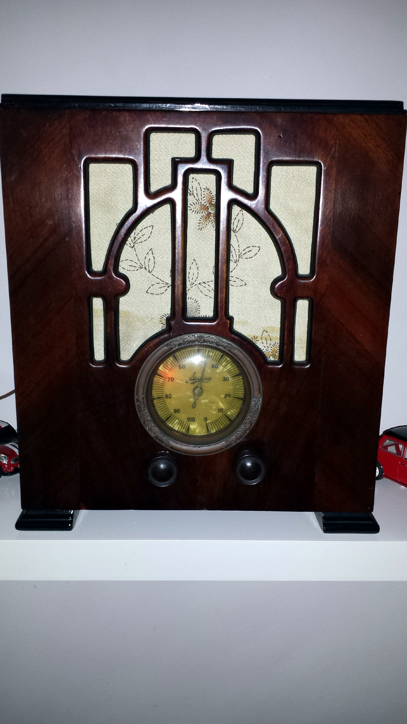 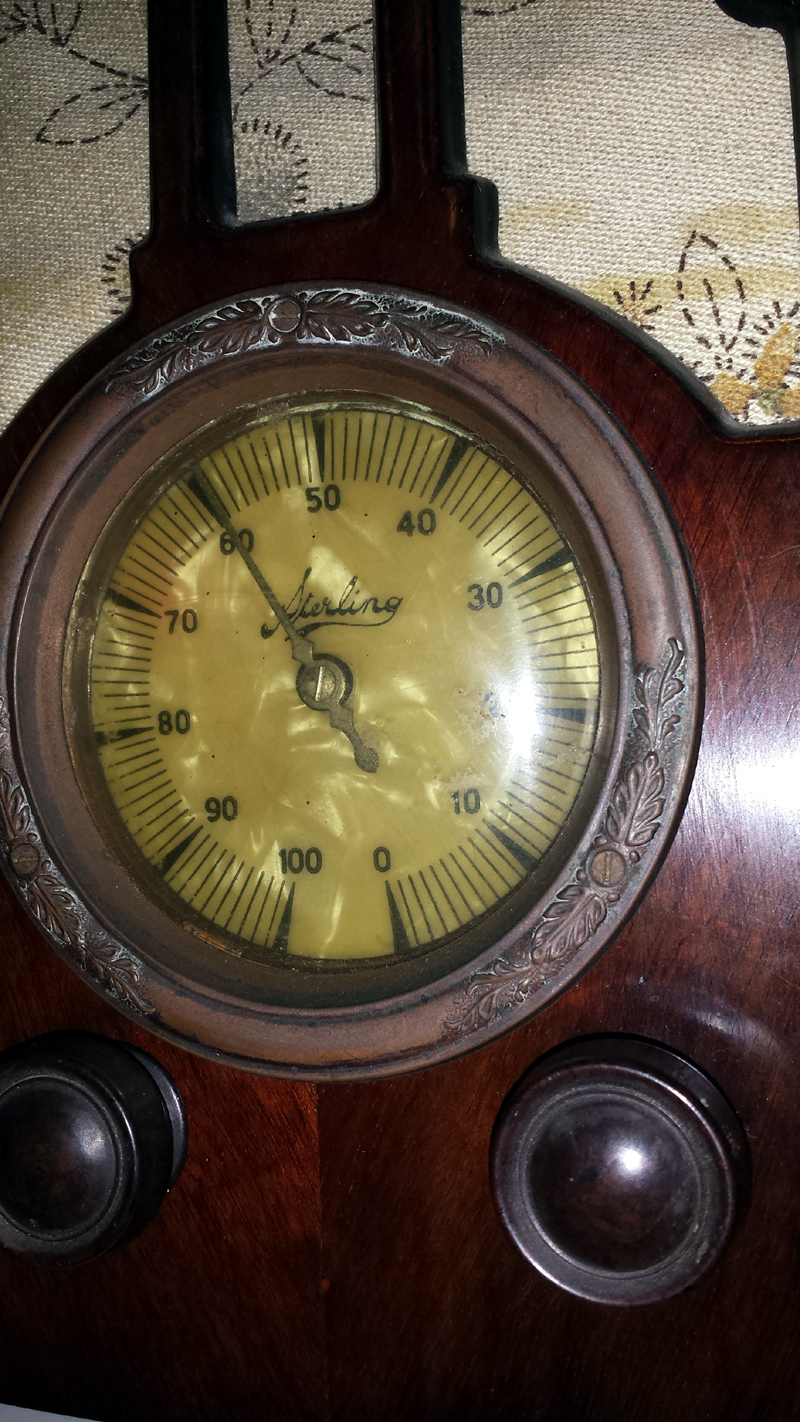 |
|
|
Return to top of page · Post #: 2 · Written at 1:15:13 AM on 4 November 2015.
|
|

|
Location: Hill Top, NSW
Member since 18 September 2015 Member #: 1801 Postcount: 2241 |
|
What other valves does it have? |
|
|
Return to top of page · Post #: 3 · Written at 1:26:34 AM on 4 November 2015.
|
|
|
|
Location: Somewhere, USA
Member since 22 October 2013 Member #: 1437 Postcount: 896 |
|
The likes of 6A7,6D6,85 I’ll bet. |
|
|
Return to top of page · Post #: 4 · Written at 2:42:54 PM on 4 November 2015.
|
|

|
Location: Melbourne, VIC
Member since 20 September 2011 Member #: 1009 Postcount: 1262 |
|
All the Sterling schematics in the AORSM are for battery sets (volume 1, pages 270 to 273). |
|
|
Return to top of page · Post #: 5 · Written at 11:05:21 AM on 5 November 2015.
|
|
|
|
Location: Hill Top, NSW
Member since 18 September 2015 Member #: 1801 Postcount: 2241 |
|
A very nice-looking radio! Hopefully you can get it going. |
|
|
Return to top of page · Post #: 6 · Written at 11:49:35 AM on 7 November 2015.
|
|
|
|
Location: Perth, WA
Member since 2 November 2015 Member #: 1815 Postcount: 17 |
|
Here are some photos of the rear of the set. 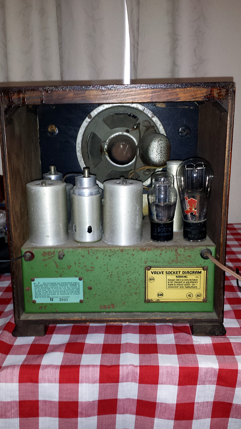 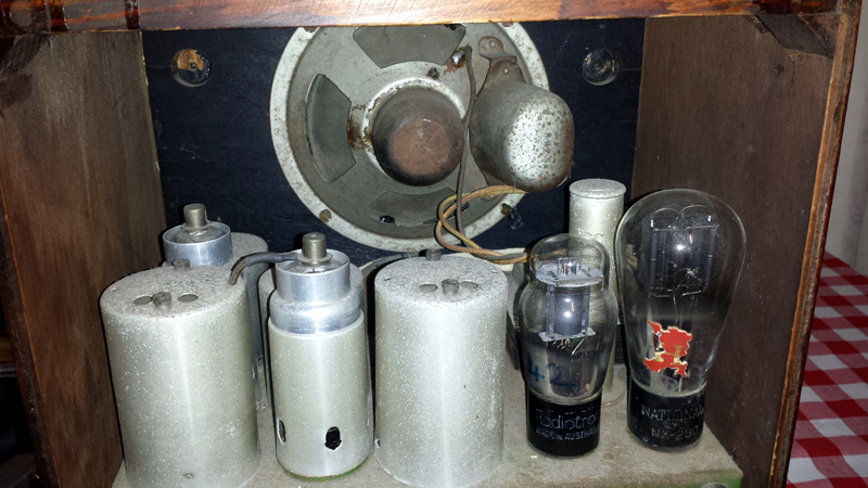 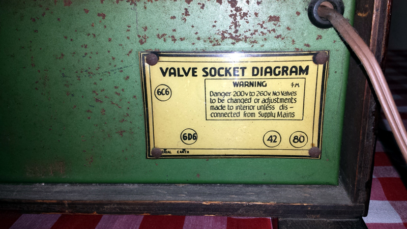 The full valve compliment is....80, 42, 6D6, 6C6 It's a superhet, and a PM speaker I've re-capped and replaced several dodgy resistors. The radio works, but performance is not good, audio output is low and distorts at much above a whisper. B+ rail is around 240 v which seems ok. 220 v on anode of output valve, similar on screen grid. |
|
|
Return to top of page · Post #: 7 · Written at 11:53:29 AM on 7 November 2015.
|
|
|
|
Location: Perth, WA
Member since 2 November 2015 Member #: 1815 Postcount: 17 |
|
Thanks mono TV.....it sounds like a 10c or 12 c according to valves used. |
|
|
Return to top of page · Post #: 8 · Written at 11:59:59 AM on 7 November 2015.
|
|
|
|
Location: Melbourne, VIC
Member since 20 September 2011 Member #: 1009 Postcount: 1262 |
|
Circuit diagram here: |
|
|
Return to top of page · Post #: 9 · Written at 8:14:21 AM on 8 November 2015.
|
|
|
|
Location: Melbourne, VIC
Member since 20 September 2011 Member #: 1009 Postcount: 1262 |
|
The Sterling in this thread only has four valves. The 10C & 12C has an extra 6C6. |
|
|
Return to top of page · Post #: 10 · Written at 10:14:40 AM on 8 November 2015.
|
|

|
Location: Wangaratta, VIC
Member since 21 February 2009 Member #: 438 Postcount: 5679 |
|
Measure the volts across R7 if it has similar? (chassis will be positive). There should be a resistor to replace the choke / field, or a choke is it there? The first filter cap should not be grounded, if there is a resistor like R7 (back bias). The worst offender for distortion is an anode bend detector running out of spec. |
|
|
Return to top of page · Post #: 11 · Written at 11:15:28 PM on 8 November 2015.
|
|
|
|
Location: Perth, WA
Member since 2 November 2015 Member #: 1815 Postcount: 17 |
|
Hi guys... Thanks for the comments. Anode bend detection, I guess that's done by the 6D6? |
|
|
Return to top of page · Post #: 12 · Written at 11:19:30 PM on 8 November 2015.
|
|
|
|
Location: Perth, WA
Member since 2 November 2015 Member #: 1815 Postcount: 17 |
|
R7....I take it that it runs from the neg side of the main filter cap to chassis, across which a voltage is developed. How many volts should I expect to measure? |
|
|
Return to top of page · Post #: 13 · Written at 12:04:34 AM on 9 November 2015.
|
|
|
|
Location: Hill Top, NSW
Member since 18 September 2015 Member #: 1801 Postcount: 2241 |
|
R7 provides the bias voltage for the type 42 output valve. At 240V on the plate, you'd be looking at about 16V across R7. |
|
|
Return to top of page · Post #: 14 · Written at 12:20:30 AM on 9 November 2015.
|
|
|
|
Location: Wangaratta, VIC
Member since 21 February 2009 Member #: 438 Postcount: 5679 |
|
What we must be careful of is that we do not know the circuit that it has. If it is back biased the resistor I call R7 from the 5 Valve circuit has to be there & goes from the centre tap of the HV winding to chassis. When the set is running properly the voltage a cross a back bias train, measured CT to chassis will be that of the grid bias of the OP tube. |
|
|
Return to top of page · Post #: 15 · Written at 12:38:27 AM on 9 November 2015.
|
|
|
|
Location: Perth, WA
Member since 2 November 2015 Member #: 1815 Postcount: 17 |
|
Thanks for the tips.....I think I'll need to get a pen and paper and draw the circuit by working out what components are hanging of the 6d6 and 42. Go hunting for resistors that may have "gone high". |
|
|
You need to be a member to post comments on this forum.
|
|

 250VDC "B voltage" chassis positive (CT is the most negative point), Has it got a choke or a resistor of perhaps 2500 Ohms: That is important as we need to see what the B+ voltage is
Sign In
Vintage Radio and Television is proudly brought to you by an era where things were built with pride and made to last.
DISCLAIMER: Valve radios and televisions contain voltages that can deliver lethal shocks. You should not attempt to work on a valve radio or other electrical appliances unless you know exactly what you are doing and have gained some experience with electronics and working around high voltages. The owner, administrators and staff of Vintage Radio & Television will accept no liability for any damage, injury or loss of life that comes as a result of your use or mis-use of information on this website. Please read our Safety Warning before using this website.
WARNING: Under no circumstances should you ever apply power to a vintage radio, television or other electrical appliance you have acquired without first having it checked and serviced by an experienced person. Also, at no time should any appliance be connected to an electricity supply if the power cord is damaged. If in doubt, do not apply power.
Shintara - Keepin' It Real · VileSilencer - Maintain The Rage