
General Discussion
Forum home - Go back to General discussion
|
Calstan 801 info needed
|
|
|
« Back ·
1 ·
Next »
|
|
|
Return to top of page · Post #: 1 · Written at 2:23:06 PM on 31 August 2014.
|
|
|
|
Location: Melbourne, VIC
Member since 19 May 2014 Member #: 1577 Postcount: 101 |
|
Hi, |
|
|
Return to top of page · Post #: 2 · Written at 12:35:16 PM on 1 September 2014.
|
|

|
Location: Perth, WA
Member since 19 November 2008 Member #: 381 Postcount: 240 |
|
I have emailed you the schematic & parts list. |
|
|
Return to top of page · Post #: 3 · Written at 12:59:57 PM on 1 September 2014.
|
|
|
|
Location: Melbourne, VIC
Member since 19 May 2014 Member #: 1577 Postcount: 101 |
|
Thanks Gary, much appreciated. |
|
|
Return to top of page · Post #: 4 · Written at 4:44:14 PM on 2 September 2014.
|
|
|
|
Location: Melbourne, VIC
Member since 19 May 2014 Member #: 1577 Postcount: 101 |
|
Found this on the web |
|
|
Return to top of page · Post #: 5 · Written at 4:50:29 PM on 2 September 2014.
|
|
|
|
Location: Melbourne, VIC
Member since 19 May 2014 Member #: 1577 Postcount: 101 |
|
This is a radiogram and is a bit different from 801/C in the AORSM. |
|
|
Return to top of page · Post #: 6 · Written at 5:41:54 PM on 2 September 2014.
|
|
|
|
Location: Perth, WA
Member since 19 November 2008 Member #: 381 Postcount: 240 |
|
A photo would help? |
|
|
Return to top of page · Post #: 7 · Written at 6:11:53 PM on 2 September 2014.
|
|

|
Location: Sydney, NSW
Member since 28 January 2011 Member #: 823 Postcount: 6933 |
|
there is a big 8 pin valve socket that I don't know what it is for. |
|
|
Return to top of page · Post #: 8 · Written at 8:08:33 PM on 2 September 2014.
|
|
|
|
Location: Melbourne, VIC
Member since 19 May 2014 Member #: 1577 Postcount: 101 |
|
Hi GTC, |
|
|
Return to top of page · Post #: 9 · Written at 8:34:43 PM on 2 September 2014.
|
|
|
|
Location: Sydney, NSW
Member since 28 January 2011 Member #: 823 Postcount: 6933 |
|
Not very easy to load photo. |
|
|
Return to top of page · Post #: 10 · Written at 9:59:07 PM on 2 September 2014.
|
|
|
|
Location: Melbourne, VIC
Member since 19 May 2014 Member #: 1577 Postcount: 101 |
|
Thanks GTC. 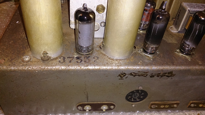 |
|
|
Return to top of page · Post #: 11 · Written at 10:25:47 PM on 2 September 2014.
|
|
|
|
Location: Melbourne, VIC
Member since 19 May 2014 Member #: 1577 Postcount: 101 |
|
Thanks Brad. |
|
|
Return to top of page · Post #: 12 · Written at 11:23:23 PM on 2 September 2014.
|
|
|
|
Location: Sydney, NSW
Member since 28 January 2011 Member #: 823 Postcount: 6933 |
|
The pair of 6AQ5 should have 10,000 ohms according to the circuit. However, there's no values for the speaker. |
|
|
Return to top of page · Post #: 13 · Written at 7:43:41 AM on 3 September 2014.
|
|
|
|
Location: Melbourne, VIC
Member since 19 May 2014 Member #: 1577 Postcount: 101 |
|
Hi GTC, 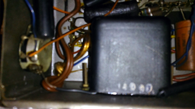 It is a sealed black box. Means anything? |
|
|
Return to top of page · Post #: 14 · Written at 11:55:23 AM on 25 January 2015.
|
|
|
|
Location: Fassifern, NSW
Member since 25 January 2015 Member #: 1687 Postcount: 24 |
|
Hi, |
|
|
« Back ·
1 ·
Next »
|
|
|
You need to be a member to post comments on this forum.
|
|

Sign In
Vintage Radio and Television is proudly brought to you by an era where things were built with pride and made to last.
DISCLAIMER: Valve radios and televisions contain voltages that can deliver lethal shocks. You should not attempt to work on a valve radio or other electrical appliances unless you know exactly what you are doing and have gained some experience with electronics and working around high voltages. The owner, administrators and staff of Vintage Radio & Television will accept no liability for any damage, injury or loss of life that comes as a result of your use or mis-use of information on this website. Please read our Safety Warning before using this website.
WARNING: Under no circumstances should you ever apply power to a vintage radio, television or other electrical appliance you have acquired without first having it checked and serviced by an experienced person. Also, at no time should any appliance be connected to an electricity supply if the power cord is damaged. If in doubt, do not apply power.
Shintara - Keepin' It Real · VileSilencer - Maintain The Rage