
General Discussion
Forum home - Go back to General discussion
|
Scharnberg Strauss model 41 circuit diagram
|
|
|
Return to top of page · Post #: 1 · Written at 4:05:16 PM on 13 July 2014.
|
|
|
|
Location: Stanmore, NSW
Member since 6 July 2014 Member #: 1599 Postcount: 29 |
|
Hi Guys, |
|
|
Return to top of page · Post #: 2 · Written at 4:14:36 PM on 13 July 2014.
|
|

|
Location: Sydney, NSW
Member since 28 January 2011 Member #: 823 Postcount: 6939 |
|
I don't have anything for Scharnberg Strauss. Schematics and information generally for that brand are hard to come by. |
|
|
Return to top of page · Post #: 3 · Written at 4:51:25 PM on 13 July 2014.
|
|
|
|
Location: Cameron Park, NSW
Member since 5 November 2010 Member #: 770 Postcount: 426 |
|
I have 4 of this model, with 2 different valve line-ups, but unfortunately I can't help with a circuit. I was able to get mine operational from basic principles. |
|
|
Return to top of page · Post #: 4 · Written at 9:40:27 AM on 14 July 2014.
|
|
|
|
Location: Stanmore, NSW
Member since 6 July 2014 Member #: 1599 Postcount: 29 |
|
Thanks Guys, appreciate the comments. I think I'll join the historical radio as well. The set works but has a hum so I'll start with replacing the caps etc. Harold, I'll check the valves and get back to you. You should see the state of this one, very rusty chassis and full of dust but still works!!! I will take a few photos as well. I'm on leave at the moment so give me a few days to send the info. |
|
|
Return to top of page · Post #: 5 · Written at 2:28:16 PM on 14 July 2014.
|
|

|
Location: Melbourne, VIC
Member since 20 September 2011 Member #: 1009 Postcount: 1262 |
|
I've been doing a bit research in to the Scharnberg Strauss brand. Scharnburg Strauss was the house brand for Ernest (not Ernst) Smith & Co, wireless retailers, who later became better known as Ernsmiths. |
|
|
Return to top of page · Post #: 6 · Written at 5:09:39 PM on 14 July 2014.
|
|
|
|
Location: Cameron Park, NSW
Member since 5 November 2010 Member #: 770 Postcount: 426 |
|
The model 41 radios on Radiomuseum are two of mine and I an currently restoring a table top radiogram. When the cabinet is finished, I will list it there, as even less is known about it. |
|
|
Return to top of page · Post #: 7 · Written at 4:53:51 PM on 19 July 2014.
|
|
|
|
Location: Stanmore, NSW
Member since 6 July 2014 Member #: 1599 Postcount: 29 |
|
Hi Harold, |
|
|
Return to top of page · Post #: 8 · Written at 5:09:07 PM on 19 July 2014.
|
|

|
Administrator
Location: Naremburn, NSW
Member since 15 November 2005 Member #: 1 Postcount: 7612 |
|
How can I post a photo here? ‾‾‾‾‾‾‾‾‾‾‾‾‾‾‾‾‾‾‾‾‾‾‾‾‾‾‾‾‾‾‾‾‾‾‾‾‾‾‾‾‾‾‾‾‾‾‾‾‾‾‾‾‾‾‾‾‾‾‾‾‾‾‾‾‾‾‾‾ A valve a day keeps the transistor away... |
|
|
Return to top of page · Post #: 9 · Written at 6:33:21 PM on 19 July 2014.
|
|
|
|
Location: Melbourne, VIC
Member since 20 September 2011 Member #: 1009 Postcount: 1262 |
|
I too would be interested in seeing some photos including some of underneath the chassis. |
|
|
Return to top of page · Post #: 10 · Written at 12:18:46 AM on 20 July 2014.
|
|
|
|
Location: Stanmore, NSW
Member since 6 July 2014 Member #: 1599 Postcount: 29 |
|
Ok photos are here, I'll see if I can work out if it has a filter choke. 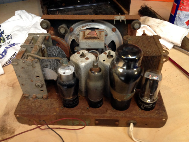 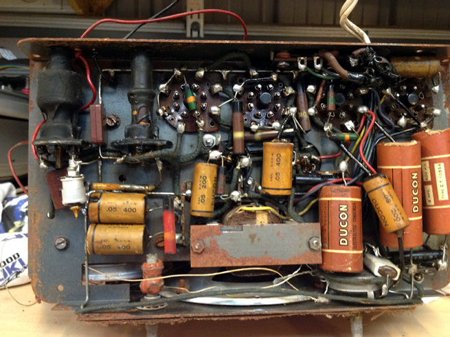 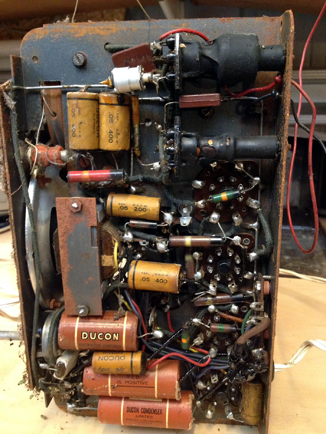 Steve. |
|
|
Return to top of page · Post #: 11 · Written at 9:53:28 AM on 20 July 2014.
|
|

|
Location: Wangaratta, VIC
Member since 21 February 2009 Member #: 438 Postcount: 5691 |
|
Really this set should not be powered those electrolytics are liable to present a s a short & burn the transformer winding out & swapping valves willy nilly can destroy them. |
|
|
Return to top of page · Post #: 12 · Written at 11:18:06 AM on 20 July 2014.
|
|
|
|
Location: Cameron Park, NSW
Member since 5 November 2010 Member #: 770 Postcount: 426 |
|
The 41 chassis does use a filter choke, it is the part with a rusty rectangle of iron holding it in, just under the speaker, yellow wire showing. This agrees with all my 41s. |
|
|
Return to top of page · Post #: 13 · Written at 12:02:28 PM on 20 July 2014.
|
|
|
|
Location: Wangaratta, VIC
Member since 21 February 2009 Member #: 438 Postcount: 5691 |
|
ECH35 and 6J8 (Feb 1938) tended to get interchanged. Tasma tended to use Philips valves. 6A8 and 6J8 will in many cases work in the same hole. But on a set like an Astor JJ and and a few others, the 6J8 will cause the band to be compressed. |
|
|
Return to top of page · Post #: 14 · Written at 5:05:03 PM on 20 July 2014.
|
|
|
|
Location: Melbourne, VIC
Member since 20 September 2011 Member #: 1009 Postcount: 1262 |
|
The unknown output valve looks like a EL3NG or something similar. It is definately cathode-biased - you can see the 25μF electrolytic (smaller one in pic) off pin 8. |
|
|
Return to top of page · Post #: 15 · Written at 5:41:50 PM on 20 July 2014.
|
|
|
|
Location: Cameron Park, NSW
Member since 5 November 2010 Member #: 770 Postcount: 426 |
|
The radio I have been looking at (ECH35 converter) is the one with an EL33 output valve, ref my post #12, and it has back bias with the cathode connected to ground. The HT voltage is only about 190 V with the transformer secondary 290 V a side, but volume is good and the radio works well. |
|
|
You need to be a member to post comments on this forum.
|
|

Sign In
Vintage Radio and Television is proudly brought to you by an era where things were built with pride and made to last.
DISCLAIMER: Valve radios and televisions contain voltages that can deliver lethal shocks. You should not attempt to work on a valve radio or other electrical appliances unless you know exactly what you are doing and have gained some experience with electronics and working around high voltages. The owner, administrators and staff of Vintage Radio & Television will accept no liability for any damage, injury or loss of life that comes as a result of your use or mis-use of information on this website. Please read our Safety Warning before using this website.
WARNING: Under no circumstances should you ever apply power to a vintage radio, television or other electrical appliance you have acquired without first having it checked and serviced by an experienced person. Also, at no time should any appliance be connected to an electricity supply if the power cord is damaged. If in doubt, do not apply power.
Shintara - Keepin' It Real · VileSilencer - Maintain The Rage