
General Discussion
Forum home - Go back to General discussion
|
Palec VCT schematic
|
|
|
« Back ·
1 ·
Next »
|
|
|
Return to top of page · Post #: 1 · Written at 9:03:26 PM on 30 April 2014.
|
|
|
|
Location: Brisbane, QLD
Member since 5 April 2014 Member #: 1547 Postcount: 14 |
|
After months of trying unsuccessfully to get a valve tester, I was lucky to find a very nice example of a Paton Palec VCT. |
|
|
Return to top of page · Post #: 2 · Written at 10:47:07 PM on 30 April 2014.
|
|

|
Location: Wangaratta, VIC
Member since 21 February 2009 Member #: 438 Postcount: 5724 |
|
There are a couple of variants of that and not a lot of caps. Resistors also fail. 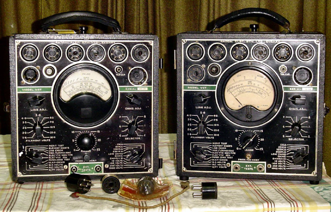 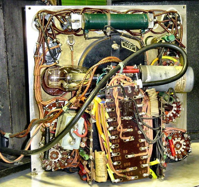 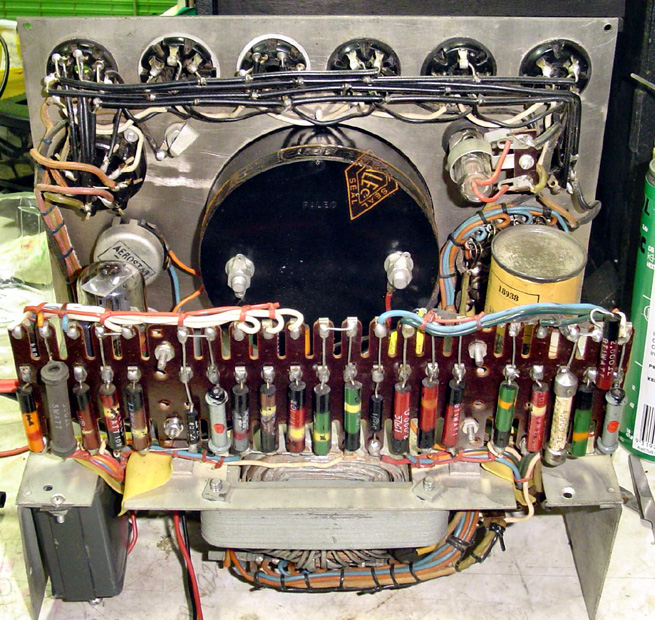 |
|
|
Return to top of page · Post #: 3 · Written at 9:37:21 PM on 2 May 2014.
|
|
|
|
Location: Brisbane, QLD
Member since 5 April 2014 Member #: 1547 Postcount: 14 |
|
Thanks for the pics. Very nice units you have. Very neat layout on the inside. Quite well designed in that aspect. If it's not too much trouble, could you email me a higher res copy of the schematic for the VCT. The one I've been working off was for the VCT-V but I don't expect there to be any changes to the circuitry over the other side of the transformer. |
|
|
« Back ·
1 ·
Next »
|
|
|
You need to be a member to post comments on this forum.
|
|
Sign In
Vintage Radio and Television is proudly brought to you by an era where things were built with pride and made to last.
DISCLAIMER: Valve radios and televisions contain voltages that can deliver lethal shocks. You should not attempt to work on a valve radio or other electrical appliances unless you know exactly what you are doing and have gained some experience with electronics and working around high voltages. The owner, administrators and staff of Vintage Radio & Television will accept no liability for any damage, injury or loss of life that comes as a result of your use or mis-use of information on this website. Please read our Safety Warning before using this website.
WARNING: Under no circumstances should you ever apply power to a vintage radio, television or other electrical appliance you have acquired without first having it checked and serviced by an experienced person. Also, at no time should any appliance be connected to an electricity supply if the power cord is damaged. If in doubt, do not apply power.
Shintara - Keepin' It Real · VileSilencer - Maintain The Rage