
General Discussion
Forum home - Go back to General discussion
|
Claritone console.
|
|
|
« Back ·
1 ·
Next »
|
|
|
Return to top of page · Post #: 1 · Written at 5:40:27 PM on 30 March 2014.
|
|
|
|
Location: Mile End, SA
Member since 23 February 2014 Member #: 1512 Postcount: 24 |
|
I've had this radio for a few years now, and have done the usual cleanup and re-cap, but with limited success. I'm hampered by not having a circuit diagram, and I'm hoping that someone here may be able to help. 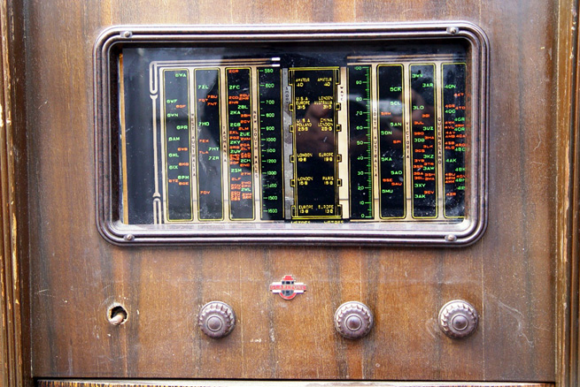 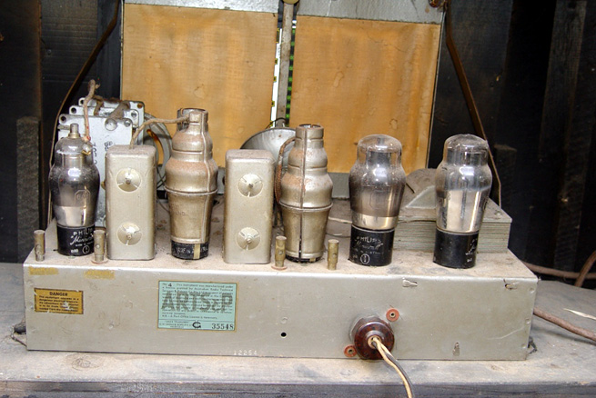 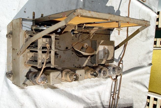 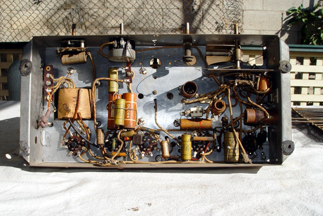 The valve lineup is from L to R: 6A8G, 6U7G, 6B6G, 6F6G and 5Y3G. Photos are from before any work was done, when it was the way it should be to start with: untouched! If anyone knows any history of this brand, and a possible age in addition to a diagram, I'd be interested. Cheers, Alan |
|
|
Return to top of page · Post #: 2 · Written at 7:54:49 PM on 30 March 2014.
|
|
|
|
Location: Blue Mountains, NSW
Member since 10 March 2013 Member #: 1312 Postcount: 401 |
|
The only reference I can find to Claritone is A W Dobbie & Co - Adelaide 1934 - 1935. |
|
|
Return to top of page · Post #: 3 · Written at 9:27:34 PM on 1 April 2014.
|
|

|
Location: Melbourne, VIC
Member since 20 September 2011 Member #: 1009 Postcount: 1263 |
|
Scraps is correct. 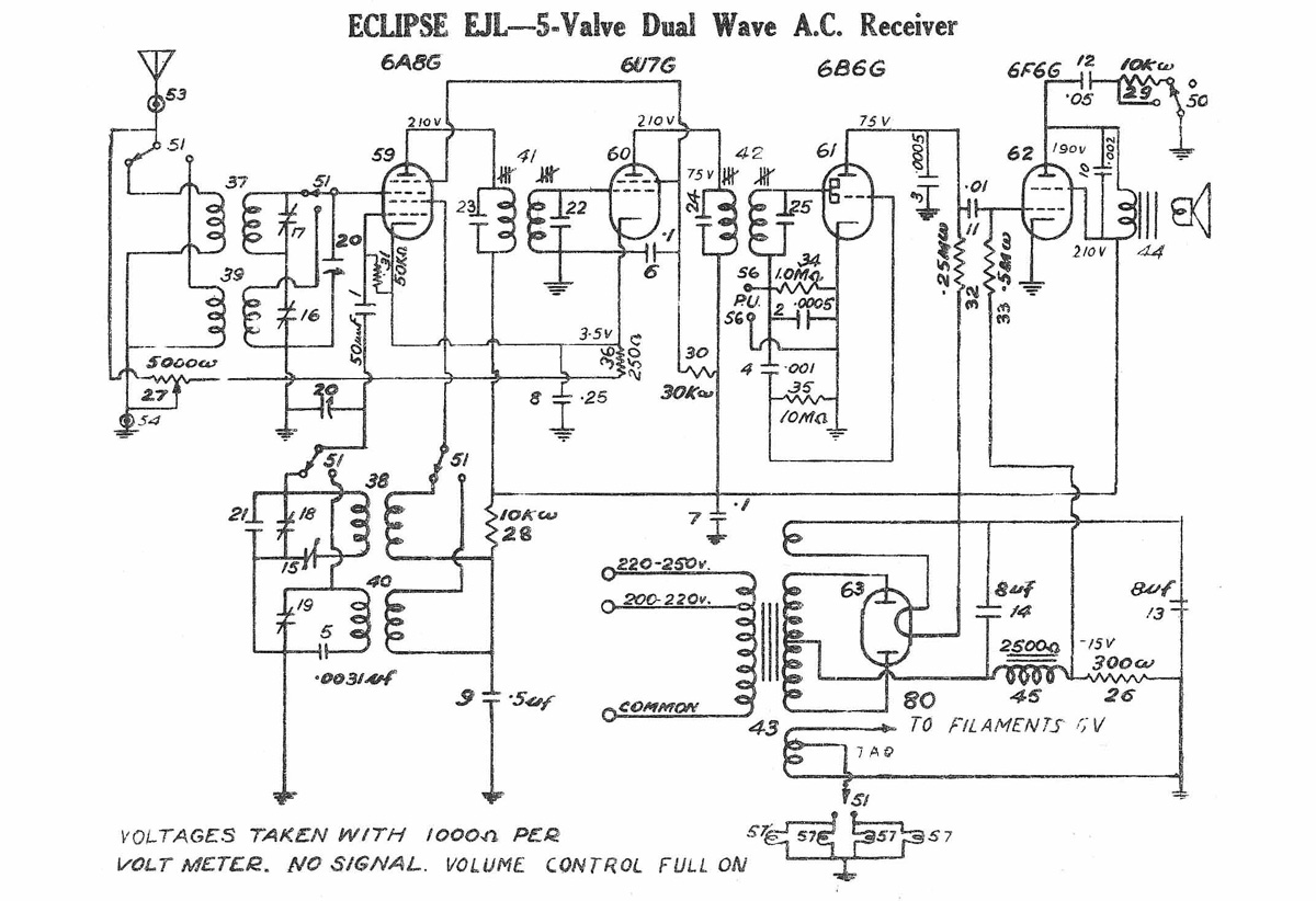 Click on circuit diagram for larger resolution |
|
|
Return to top of page · Post #: 4 · Written at 10:18:45 PM on 4 April 2014.
|
|
|
|
Location: Mile End, SA
Member since 23 February 2014 Member #: 1512 Postcount: 24 |
|
Thank you for that. |
|
|
Return to top of page · Post #: 5 · Written at 10:10:35 AM on 5 April 2014.
|
|
|
|
Location: Melbourne, VIC
Member since 20 September 2011 Member #: 1009 Postcount: 1263 |
|
The Eclipse circuit uploaded to this thread is for a guide only. It was chosen because I think the Claritone may be using an Eclipse chassis. Also, comparing the photos of underneath the chassis to the schematic looks pretty close, right down to the large 10 meg resistor between the grid of the 6B6G to ground. The volume control set up in the schematic is something I haven't seen before. It is best to compare the chassis with the circuit before working on it. It may well be that the Claritone chassis is based on the Eclipse circuit but with some differences. |
|
|
Return to top of page · Post #: 6 · Written at 10:57:46 AM on 5 April 2014.
|
|
|
|
Location: NSW
Member since 10 June 2010 Member #: 681 Postcount: 1408 |
|
"The volume control set up in the schematic is something I haven't seen before." |
|
|
« Back ·
1 ·
Next »
|
|
|
You need to be a member to post comments on this forum.
|
|
Sign In
Vintage Radio and Television is proudly brought to you by an era where things were built with pride and made to last.
DISCLAIMER: Valve radios and televisions contain voltages that can deliver lethal shocks. You should not attempt to work on a valve radio or other electrical appliances unless you know exactly what you are doing and have gained some experience with electronics and working around high voltages. The owner, administrators and staff of Vintage Radio & Television will accept no liability for any damage, injury or loss of life that comes as a result of your use or mis-use of information on this website. Please read our Safety Warning before using this website.
WARNING: Under no circumstances should you ever apply power to a vintage radio, television or other electrical appliance you have acquired without first having it checked and serviced by an experienced person. Also, at no time should any appliance be connected to an electricity supply if the power cord is damaged. If in doubt, do not apply power.
Shintara - Keepin' It Real · VileSilencer - Maintain The Rage