Welcome to Australia's only Vintage Radio and Television discussion forums. You are not logged in. Please log in below, apply for an account or retrieve your password.
Australian Vintage Radio Forums
  Home  ·  About Us  ·  Discussion Forums  ·  Glossary  ·  Outside Links  ·  Policies  ·  Services Directory  ·  Safety Warnings  ·  Tutorials

General Discussion

Forum home - Go back to General discussion

 Mystery Stromberg-Carlson chassis ID and restore?
« Back · 1 · Next »
 Return to top of page · Post #: 1 · Written at 10:08:43 AM on 22 January 2012.
Clockmeister's Gravatar
 Location: Albany, WA
 Member since 20 January 2012
 Member #: 1068
 Postcount: 25

I've picked up a mystery SC chassis which was mounted in a wooden draw style radiogram piece which would have looked a bit like this http://vintage-radio.com.au/photos/stromberg-carlson-radiogram-2-310810.jpg. However, if I could get the radio working again I have an idea for a project, to house it in a custom case and listen to the cricket and footy in my workshop but that is a long way off I think, looking at the radio.

The radio has 6 valves which, best I can make out, are;

Radiotron 6V4
Miniwatt 6AQ5 x2 (best I can make out is that they are the same, one is unreadable and has a crack, the other barely readable)
Mullard 12AX7
Miniwatt 6N8
Miniwatt? unreadable (the one closest to the ferrite rod)

There is a big resistor just near the electrolytic caps which looks and smells burnt. Ohmmeter reads 21 ohms on it in situ.

Power transformer is a Ferguson, looks like PF170 stamped on top and 5.68 stamped on the side.

Anyway, here are some pics
http://tinyurl.com/6pnfocb.

Can anyone shed some light on the age/model and hopefully schematics?
Also, there doesn't seem to be an audio transformer, were the speakers wired directly or would there have been an external audio transformer?

Sorry for the noob questions, I'm familiar with digital electronics but this valve stuff is new to me.

Clocky.


 Return to top of page · Post #: 2 · Written at 11:40:41 AM on 22 January 2012.
GTC's avatar
 GTC
 Location: Sydney, NSW
 Member since 28 January 2011
 Member #: 823
 Postcount: 6686

Welcome to the forum and to valve radios.

Your Flickr link doesn't work, probably because it has the . character in it and the forum software fiddles with
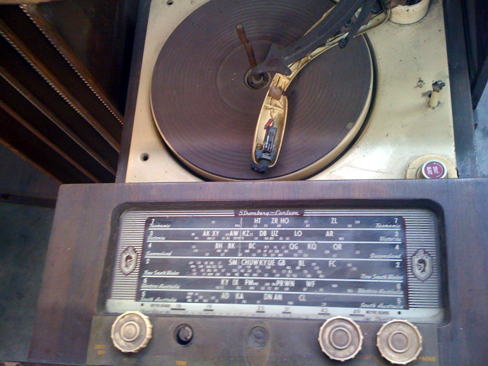
 . to prevent email address harvesting. Suggest that you convert the link to a tinyurl one and re-post.

Meanwhile, your valve line-up seems to match SC models 67A11 and 68A21 of 1958, with the latter being a dual wave radiogram.

The line-up for those models is: 6V4, 6BE6, 6N8, 12AX7, 6AQ5X2.

The two 6AQ5s form a push-pull pair requiring a centre-tapped transformer, which was most likely mounted on the speaker.

The schematic for model 68A21shows a twin-speaker arrangement in two options: 2 x 6 inch speakers in parallel with one output transformer, or an 8 inch and a 5 inch pair with two transformers and a .01 μF cap for crossover.

If you unhide your email address in your member profile, I'll send you the schematics.


 Return to top of page · Post #: 3 · Written at 12:00:54 PM on 22 January 2012.
Clockmeister's Gravatar
 Location: Albany, WA
 Member since 20 January 2012
 Member #: 1068
 Postcount: 25

Thanks for that, the link to the pics is http://tinyurl.com/6pnfocb.

I think this is a single band model, it has 3 tone select switch, phono/radio select as well as power/volume control and the tuning knob - if it helps.

I've edited the original post too. My email address should be visible now I hope, thanks for the schematics in advance.


 Return to top of page · Post #: 4 · Written at 3:46:12 PM on 22 January 2012.
GTC's avatar
 GTC
 Location: Sydney, NSW
 Member since 28 January 2011
 Member #: 823
 Postcount: 6686

Okay, schematics sent. Both have a 3 position tone switch.

From the rust evident in the pics it seems that radio has been exposed to quite a bit of moisture (and/or salt-laden air), but we've seen worse that have been brought back to life.

That power supply resistor is shown as 21 ohms. Yours may be cooked because of a bad filter electrolytic. Hopefully the transformer's secondary is still okay. If the tranny has been cooked you'll definitely be able to smell it. A continuity check is in order.

The usual routine with old stuff is to replace the electros as a matter of course, and the paper caps, too.

Moisture/dampness can cause the fine wire in the IF transformers to corrode and go open circuit. With a bit of luck that won't have happened to your set.

With your apparent technical background this may not need to be said but, you will be dealing with high voltages so be careful as you go. Don't power it up until you have replaced bad components (including wiring where appropriate), and checked for shorts to chassis and for shorted valves.

Best to power these restored sets up via a Variac while watching the HT voltage and current. Some use a current limiter (and short circuit indicator) in the form of a 240v light bulb in series with the active of the mains cord.

Don't power up the set without an output transformer and load in circuit. Valves need to operate into the appropriate impedance or they will usually run red in the face and self destruct, frequently taking other stuff with them.


 Return to top of page · Post #: 5 · Written at 2:00:01 AM on 23 January 2012.
Clockmeister's Gravatar
 Location: Albany, WA
 Member since 20 January 2012
 Member #: 1068
 Postcount: 25

The schematic helped greatly. Seems the rectifier tube has a dead short between the output and the input.

I replaced the shorted 6V4 with some diodes. All I had on hand were 1N4004's so I put a couple in series to increase their operating voltage. Having done that, the power supply is much happier now and runs cool. I replaced the burnt resistor with a suitable replacement and snipped a paper filter cap that was getting hot temporarily until I can get all the caps needed to recap this old girl.

One of the 6AQ5's is broken and needs replacing and the other looks like it may have seen better days also but I don't have any spares.

I used a temporary output transformer and hooked up a speaker and powered the unit up (after doing basic voltage/short checks etc)). Most surprisingly it happened to be on a station and was working, albeit at low volume. Still, there is life.

The tuning stages seem to work quite well, with good selectivity and reception.

I presume that the 6AQ5's would be operating in a push/pull arrangement, does that mean that if one tube is out (as is the case here) the output very low or should I be looking for another problem?

Recommendations for a suitable output transformer and a source for reasonably priced valves around Perth/Australia would be appreciated. Ebay lists plenty, but as I'm in the process of moving, ordering from overseas isn't going to be possible.


Thanks for any help.

Clocky.


 Return to top of page · Post #: 6 · Written at 4:44:51 PM on 23 January 2012.
Brad's avatar
 Administrator
 Location: Naremburn, NSW
 Member since 15 November 2005
 Member #: 1
 Postcount: 7300

Just to confirm, Flickr and some other sites use the . symbol as a special character in their querystrings. It's a pain and fairly silly, as there's plenty of other ways to achieve what they want to do but we are stuck with it. A short URL is a good way around the problem. All . symbols here render as images to try and trick spam robots into thinking that a posted e-mail address isn't.


‾‾‾‾‾‾‾‾‾‾‾‾‾‾‾‾‾‾‾‾‾‾‾‾‾‾‾‾‾‾‾‾‾‾‾‾‾‾‾‾‾‾‾‾‾‾‾‾‾‾‾‾‾‾‾‾‾‾‾‾‾‾‾‾‾‾‾‾
A valve a day keeps the transistor away...

 
 Return to top of page · Post #: 7 · Written at 5:42:23 PM on 23 January 2012.
GTC's avatar
 GTC
 Location: Sydney, NSW
 Member since 28 January 2011
 Member #: 823
 Postcount: 6686

Recommendations for a suitable output transformer

According to some data I have, a pair of 6AQ5s in push-pull should be happy working into an impedance of around 10,000 ohms.

You could use a universal output transformer such as:

http://evatco.com.au/hamunispec.htm

... which allows you to configure a primary (valve side) of 10Kohms and a secondary (speaker side) of any impedance between 1.5 to 15 ohms. Universals are pricey, but convenient.

and a source for reasonably priced valves around Perth/Australia would be appreciated.

Try Steve Savell (in WA) via: http://www.goznet.com/contact.html.


 Return to top of page · Post #: 8 · Written at 8:39:43 PM on 25 January 2012.
Airzone's Gravatar
 Location: Maclean, NSW
 Member since 30 May 2008
 Member #: 291
 Postcount: 341

I get my transformers from here:
http://www.xtalman.com/headsets.html


 Return to top of page · Post #: 9 · Written at 5:36:55 PM on 4 February 2012.
Clockmeister's Gravatar
 Location: Albany, WA
 Member since 20 January 2012
 Member #: 1068
 Postcount: 25

Thanks everyone, I've noted the links for future reference.
In case anyone is interested in the progress of getting this radio working, I was reading a webpage which mentions using a cheap M1115 PA transformer from Altronics as the output transformer. Given that the transformers are barely $12 I thought this would be good enough for testing purposes at least so I ordered one.

I picked up a couple of tested 6AQ5's off ebay for cheap.

I replaced the electrolytic and paper caps, attached the OPT, popped in the pair of 6AQ5(A)'s and fired her up.

Well, there was music, and it was loud but I noticed that the two 6AQ5'd were redplating after 30 seconds or so. I rechecked the voltages and found the B+ to be about 300V which is presumably what is causing the problem. Resistances seem to be within spec as far as the power circuit goes so I assumed that the higher voltage was due to using rectifier diodes instead of the 6V4 tube. I had a couple of 820 ohm ceramic resistors handy so I put them in series on the DC side of the diodes.

The voltage is now stable at 200V and the radio is working quite well apart from some hum and the volume pot being a bit scratchy.

I'll replace diodes with a 6V4 and recheck the voltages and clean it up a bit more... it sounds so much better than it looks!


« Back · 1 · Next »
 You need to be a member to post comments on this forum.

Sign In

Username:
Password:
 Keep me logged in.
Do not tick box on a computer with public access.