
General Discussion
Forum home - Go back to General discussion
|
STC 402-3
|
|
|
Return to top of page · Post #: 1 · Written at 3:45:47 PM on 27 December 2011.
|
|
|
|
Location: Maclean, NSW
Member since 30 May 2008 Member #: 291 Postcount: 341 |
|
Does anyone have an STC 402-3 wood case radio, I have a circuit for it but the valves do not match to circuit. 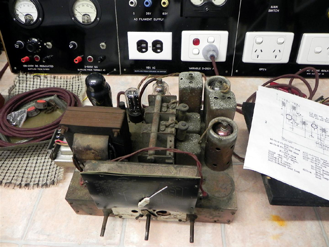 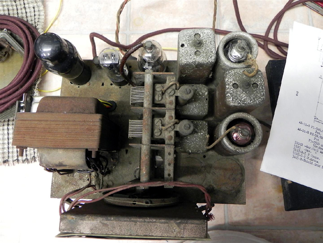 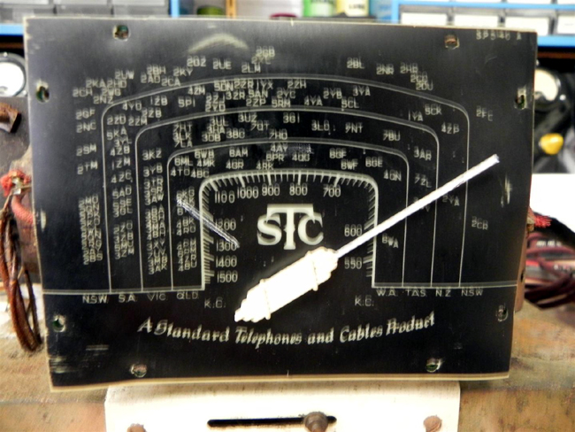 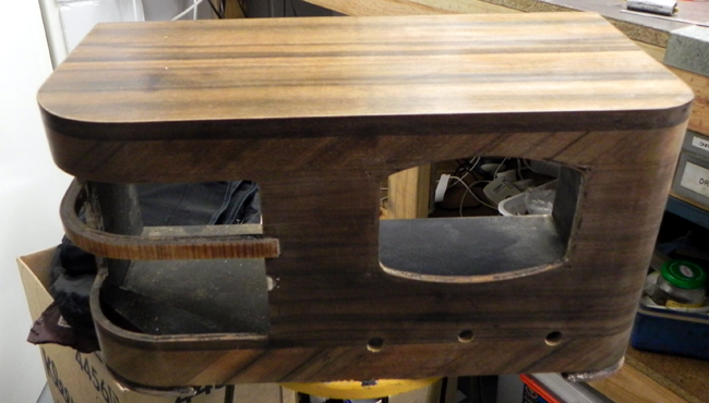 |
|
|
Return to top of page · Post #: 2 · Written at 9:22:27 PM on 27 December 2011.
|
|

|
Location: Wangaratta, VIC
Member since 21 February 2009 Member #: 438 Postcount: 5720 |
|
Might pay to list what is in there. Often during the war years, strange things happened to keep sets going. |
|
|
Return to top of page · Post #: 3 · Written at 10:02:53 PM on 27 December 2011.
|
|
|
|
Location: Maclean, NSW
Member since 30 May 2008 Member #: 291 Postcount: 341 |
|
Hi Marcc |
|
|
Return to top of page · Post #: 4 · Written at 9:04:05 AM on 28 December 2011.
|
|
|
|
Location: Wangaratta, VIC
Member since 21 February 2009 Member #: 438 Postcount: 5720 |
|
I would consider that rare but not unusual. |
|
|
Return to top of page · Post #: 5 · Written at 11:30:00 PM on 28 December 2011.
|
|
|
|
Location: Maclean, NSW
Member since 30 May 2008 Member #: 291 Postcount: 341 |
|
Looks like a small mains transformer has been fitted underneath the chassis, there is a 5Y3GT rectifier there also on top. |
|
|
Return to top of page · Post #: 6 · Written at 11:31:49 PM on 28 December 2011.
|
|

|
Administrator
Location: Naremburn, NSW
Member since 15 November 2005 Member #: 1 Postcount: 7633 |
|
Photos uploaded. ‾‾‾‾‾‾‾‾‾‾‾‾‾‾‾‾‾‾‾‾‾‾‾‾‾‾‾‾‾‾‾‾‾‾‾‾‾‾‾‾‾‾‾‾‾‾‾‾‾‾‾‾‾‾‾‾‾‾‾‾‾‾‾‾‾‾‾‾ A valve a day keeps the transistor away... |
|
|
Return to top of page · Post #: 7 · Written at 1:23:41 AM on 29 December 2011.
|
|
|
|
Location: Wangaratta, VIC
Member since 21 February 2009 Member #: 438 Postcount: 5720 |
|
The stuffup may be in the area of the output tube. |
|
|
Return to top of page · Post #: 8 · Written at 9:04:17 AM on 29 December 2011.
|
|
|
|
Location: NSW
Member since 10 June 2010 Member #: 681 Postcount: 1408 |
|
I have a 632 (1939) with a similar cabinet, with one of the bars across the speaker opening delaminated and pieces of the finishing veneer missing. So I wonder if you have considered yet how to replace the missing bar on your radio and the type of timber in the finishing veneer. |
|
|
Return to top of page · Post #: 9 · Written at 9:15:35 AM on 29 December 2011.
|
|

|
Location: Sydney, NSW
Member since 28 January 2011 Member #: 823 Postcount: 6956 |
|
Nice looking test bench setup. Would like to see more of it. |
|
|
Return to top of page · Post #: 10 · Written at 1:14:53 PM on 29 December 2011.
|
|
|
|
Location: Wangaratta, VIC
Member since 21 February 2009 Member #: 438 Postcount: 5720 |
|
That is a fairly common cabinet for STC around that time. |
|
|
Return to top of page · Post #: 11 · Written at 10:15:06 PM on 30 December 2011.
|
|
|
|
Location: Maclean, NSW
Member since 30 May 2008 Member #: 291 Postcount: 341 |
|
Well this thread has a great response from you boys, well done. |
|
|
Return to top of page · Post #: 12 · Written at 10:46:14 PM on 30 December 2011.
|
|
|
|
Administrator
Location: Naremburn, NSW
Member since 15 November 2005 Member #: 1 Postcount: 7633 |
|
Feel free to send photos. Just start another thread in this forum when ready. I'd better get my act together and tidy my workshop up. ‾‾‾‾‾‾‾‾‾‾‾‾‾‾‾‾‾‾‾‾‾‾‾‾‾‾‾‾‾‾‾‾‾‾‾‾‾‾‾‾‾‾‾‾‾‾‾‾‾‾‾‾‾‾‾‾‾‾‾‾‾‾‾‾‾‾‾‾ A valve a day keeps the transistor away... |
|
|
Return to top of page · Post #: 13 · Written at 3:42:50 PM on 1 January 2012.
|
|
|
|
Location: NSW
Member since 10 June 2010 Member #: 681 Postcount: 1408 |
|
Hello Airzone 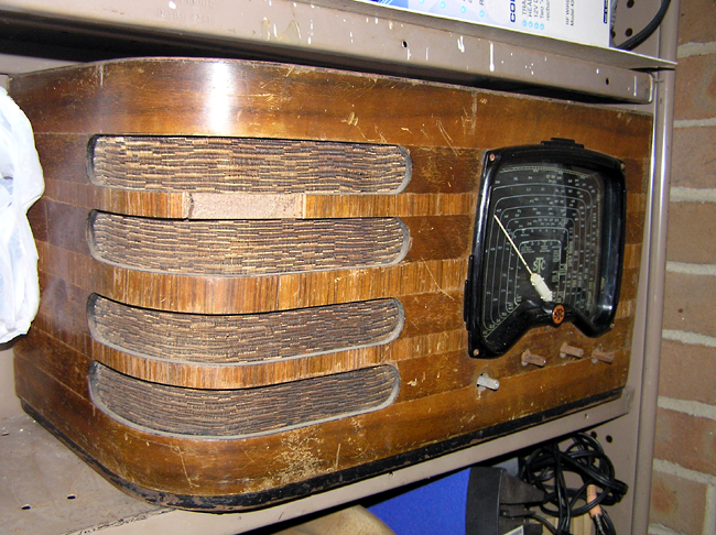 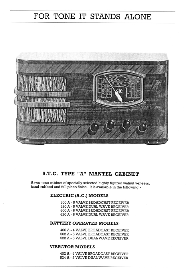 |
|
|
Return to top of page · Post #: 14 · Written at 9:55:55 AM on 19 April 2012.
|
|
|
|
Location: NSW
Member since 10 June 2010 Member #: 681 Postcount: 1408 |
|
While working on the STC 632 found a cabinet label in pieces and managed to piece it together. Never found anything like this before so thought it was worth posting. 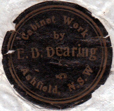 |
|
|
Return to top of page · Post #: 15 · Written at 1:16:31 PM on 19 April 2012.
|
|
|
|
Location: Sydney, NSW
Member since 28 January 2011 Member #: 823 Postcount: 6956 |
|
^ Yes, definitely worth posting. |
|
|
You need to be a member to post comments on this forum.
|
|

 exemail.com.au if you want photos or if anyone else is interested I will ask Brad if I can start a thread on members test benches and if he can place the photos up for us all to see. I have a test bench for sale, I will place the advert in the for sale forum.
Sign In
Vintage Radio and Television is proudly brought to you by an era where things were built with pride and made to last.
DISCLAIMER: Valve radios and televisions contain voltages that can deliver lethal shocks. You should not attempt to work on a valve radio or other electrical appliances unless you know exactly what you are doing and have gained some experience with electronics and working around high voltages. The owner, administrators and staff of Vintage Radio & Television will accept no liability for any damage, injury or loss of life that comes as a result of your use or mis-use of information on this website. Please read our Safety Warning before using this website.
WARNING: Under no circumstances should you ever apply power to a vintage radio, television or other electrical appliance you have acquired without first having it checked and serviced by an experienced person. Also, at no time should any appliance be connected to an electricity supply if the power cord is damaged. If in doubt, do not apply power.
Shintara - Keepin' It Real · VileSilencer - Maintain The Rage