
General Discussion
Forum home - Go back to General discussion
|
airzone radio 6 volts ?
|
|
|
« Back ·
1 ·
Next »
|
|
|
Return to top of page · Post #: 1 · Written at 7:26:07 AM on 5 August 2011.
|
|

|
Location: Noosa, QLD
Member since 31 December 2010 Member #: 799 Postcount: 302 |
|
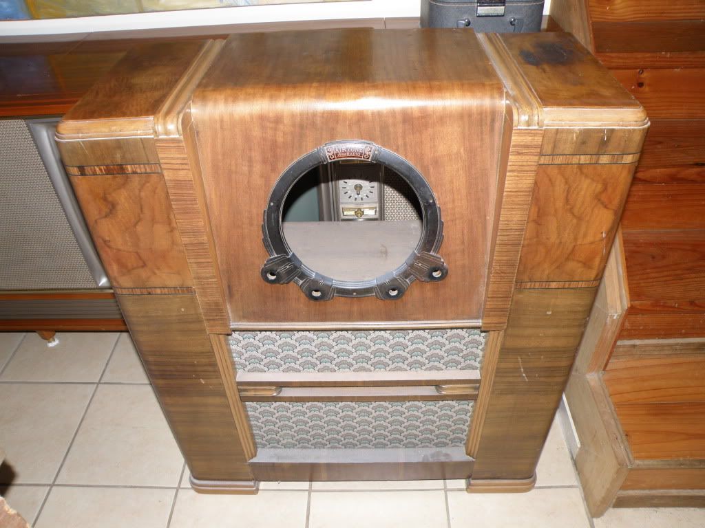
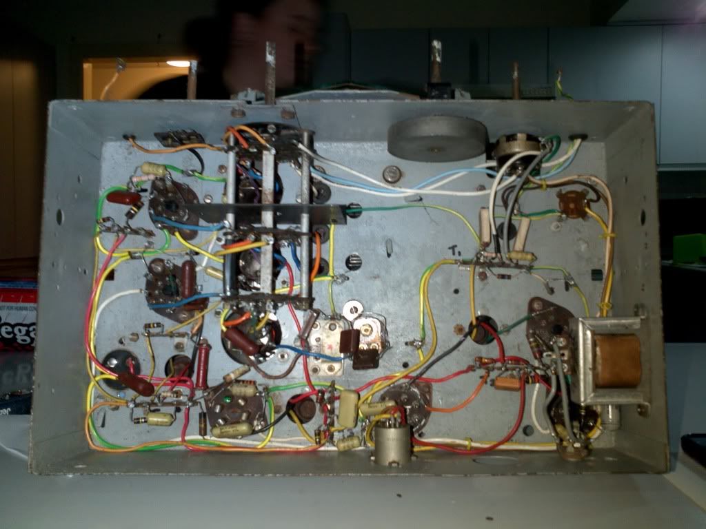
Hi guys can anyone tell me much about this unit? is it 6 volt as there is no transformer. is there anyone that can repair or redo the numbers on the glass thanks |
|
|
Return to top of page · Post #: 2 · Written at 9:32:27 AM on 5 August 2011.
|
|

|
Location: Wangaratta, VIC
Member since 21 February 2009 Member #: 438 Postcount: 5724 |
|
The Dymo tape is interesting....someone was trying to work out something. |
|
|
Return to top of page · Post #: 3 · Written at 8:33:39 PM on 5 August 2011.
|
|
|
|
Location: NSW
Member since 6 October 2010 Member #: 745 Postcount: 15 |
|
Try using this link to identify your chassis |
|
|
Return to top of page · Post #: 4 · Written at 9:17:03 AM on 6 August 2011.
|
|
|
|
Location: Noosa, QLD
Member since 31 December 2010 Member #: 799 Postcount: 302 |
|
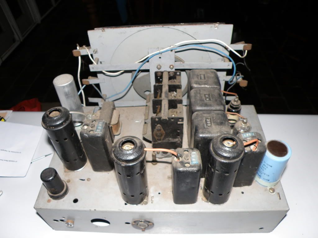
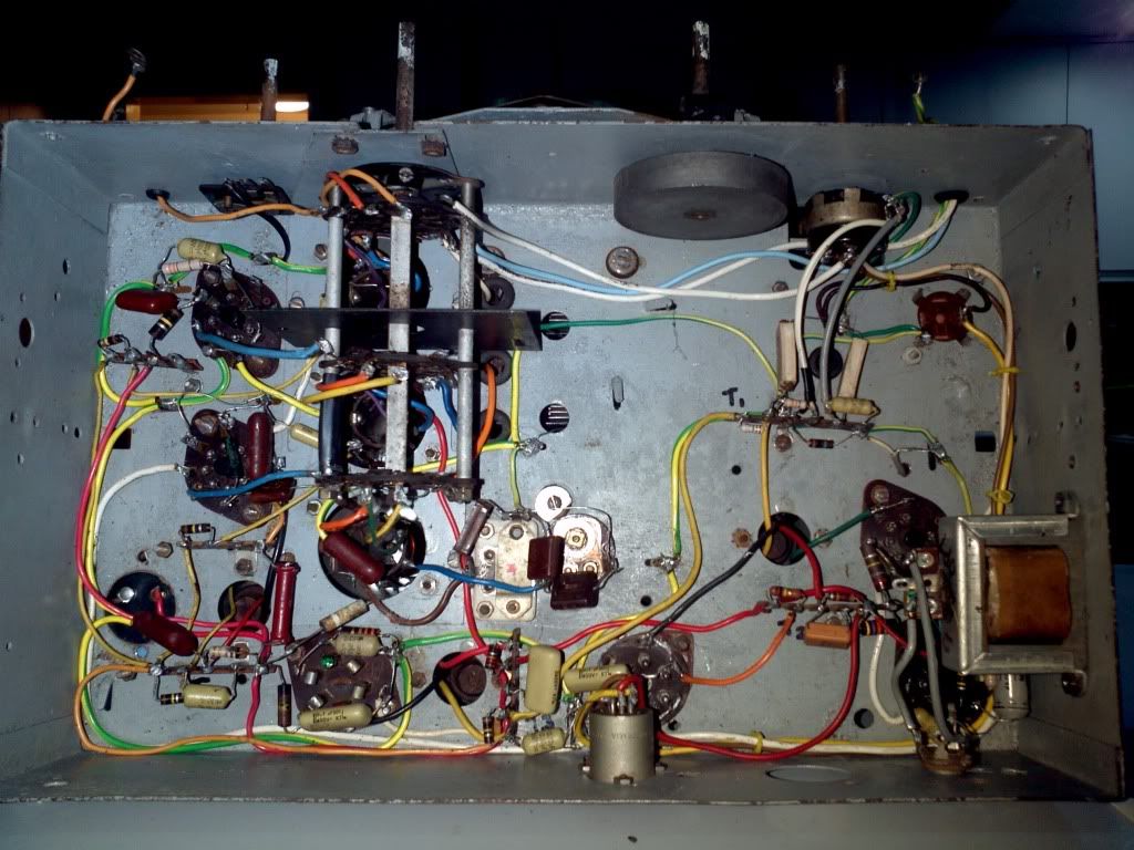
Here are some piks of the bottom and no on back R2867 |
|
|
Return to top of page · Post #: 5 · Written at 9:35:33 AM on 6 August 2011.
|
|
|
|
Location: NSW
Member since 6 October 2010 Member #: 745 Postcount: 15 |
|
That chassis looks home made by the wiring, I've never seen yellow/green earth wire in a commercial set before |
|
|
Return to top of page · Post #: 6 · Written at 8:12:59 PM on 6 August 2011.
|
|
|
|
Location: Wangaratta, VIC
Member since 21 February 2009 Member #: 438 Postcount: 5724 |
|
It could also be a case of whoever did it was not terribly fussed as to what they used & scrounged the wire from mains cables & whatever. |
|
|
Return to top of page · Post #: 7 · Written at 3:00:21 PM on 7 August 2011.
|
|
|
|
Location: NSW
Member since 10 June 2010 Member #: 681 Postcount: 1408 |
|
There is something similar in Siliconchip archives which might help |
|
|
Return to top of page · Post #: 8 · Written at 3:17:46 PM on 7 August 2011.
|
|
|
|
Location: Wangaratta, VIC
Member since 21 February 2009 Member #: 438 Postcount: 5724 |
|
Know the ins & outs of that one. I fixed it.. |
|
|
Return to top of page · Post #: 9 · Written at 8:12:08 PM on 7 August 2011.
|
|
|
|
Location: Noosa, QLD
Member since 31 December 2010 Member #: 799 Postcount: 302 |
|
Thanks guys |
|
|
Return to top of page · Post #: 10 · Written at 9:55:48 PM on 7 August 2011.
|
|
|
|
Location: Wangaratta, VIC
Member since 21 February 2009 Member #: 438 Postcount: 5724 |
|
The terminals suggest yes but I would not dare fire that thing up without going through it with a "tooth pick ,comb & circuit" to find out what has been done to it and if it is wrong. Often sets are abondoned because of a fault or stuff up. You need to look to find out which one it was. |
|
|
« Back ·
1 ·
Next »
|
|
|
You need to be a member to post comments on this forum.
|
|
 marc did you work on this exact one? I would like to test it but not sure how to wire it up have you got a diagram that can help thanks and is it 6 volt? thanks
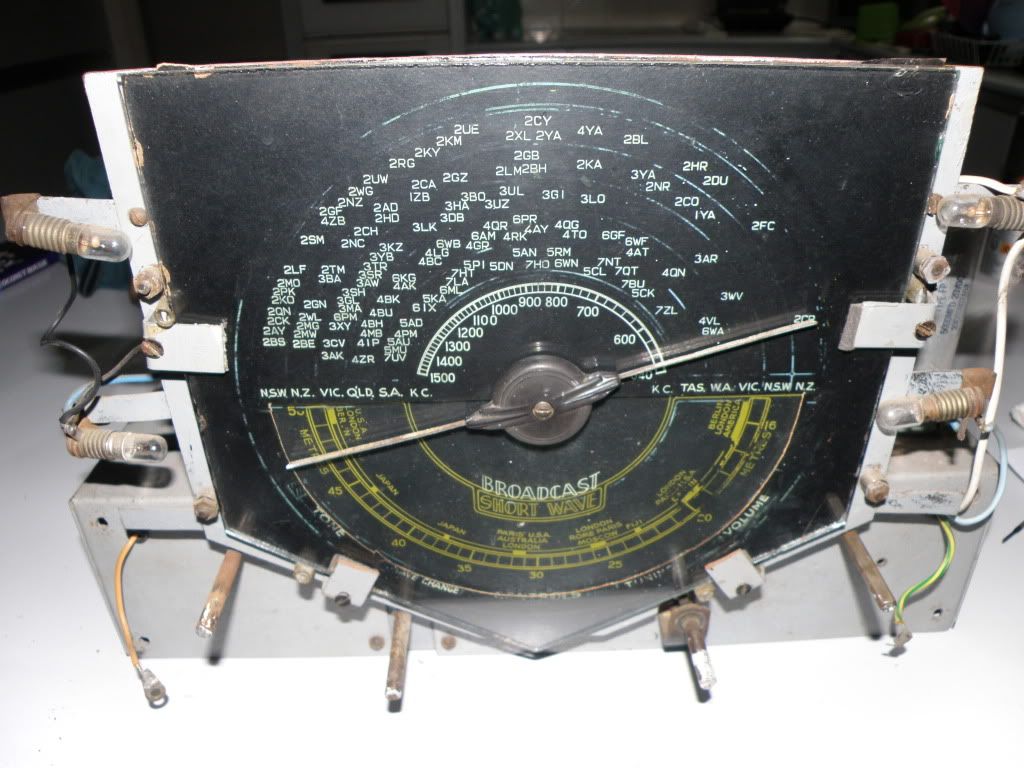
Sign In
Vintage Radio and Television is proudly brought to you by an era where things were built with pride and made to last.
DISCLAIMER: Valve radios and televisions contain voltages that can deliver lethal shocks. You should not attempt to work on a valve radio or other electrical appliances unless you know exactly what you are doing and have gained some experience with electronics and working around high voltages. The owner, administrators and staff of Vintage Radio & Television will accept no liability for any damage, injury or loss of life that comes as a result of your use or mis-use of information on this website. Please read our Safety Warning before using this website.
WARNING: Under no circumstances should you ever apply power to a vintage radio, television or other electrical appliance you have acquired without first having it checked and serviced by an experienced person. Also, at no time should any appliance be connected to an electricity supply if the power cord is damaged. If in doubt, do not apply power.
Shintara - Keepin' It Real · VileSilencer - Maintain The Rage