
General Discussion
Forum home - Go back to General discussion
|
radio identification for a friend
|
|
|
« Back ·
1 ·
Next »
|
|
|
Return to top of page · Post #: 1 · Written at 7:58:53 PM on 16 July 2011.
|
|

|
Location: Noosa, QLD
Member since 31 December 2010 Member #: 799 Postcount: 302 |
|
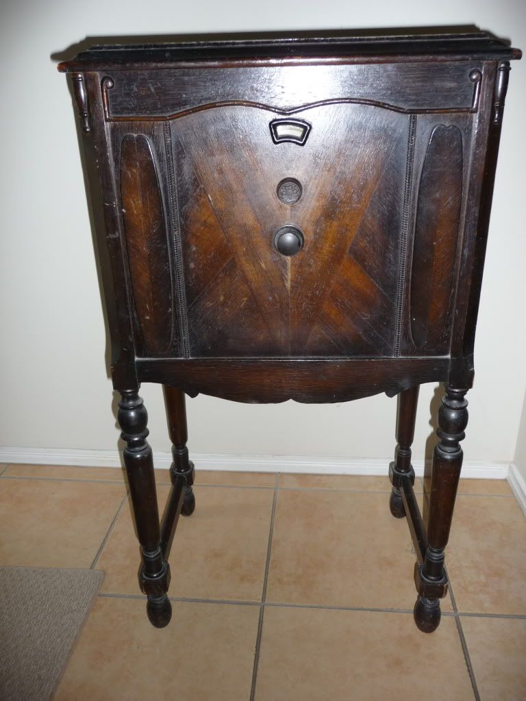
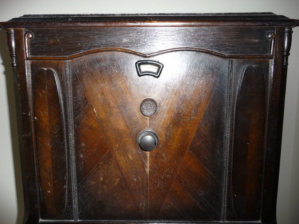
Hi guys I have an unknown radio its a family friends and they would like me to get it cleaned up and going for them but I'm not sure what is it any ideas piks below and its missing a valve |
|
|
Return to top of page · Post #: 2 · Written at 12:56:31 AM on 17 July 2011.
|
|

|
Location: Wangaratta, VIC
Member since 21 February 2009 Member #: 438 Postcount: 5724 |
|
A challenge would be part of the answer. |
|
|
Return to top of page · Post #: 3 · Written at 1:48:16 PM on 17 July 2011.
|
|

|
Location: Sydney, NSW
Member since 28 January 2011 Member #: 823 Postcount: 6956 |
|
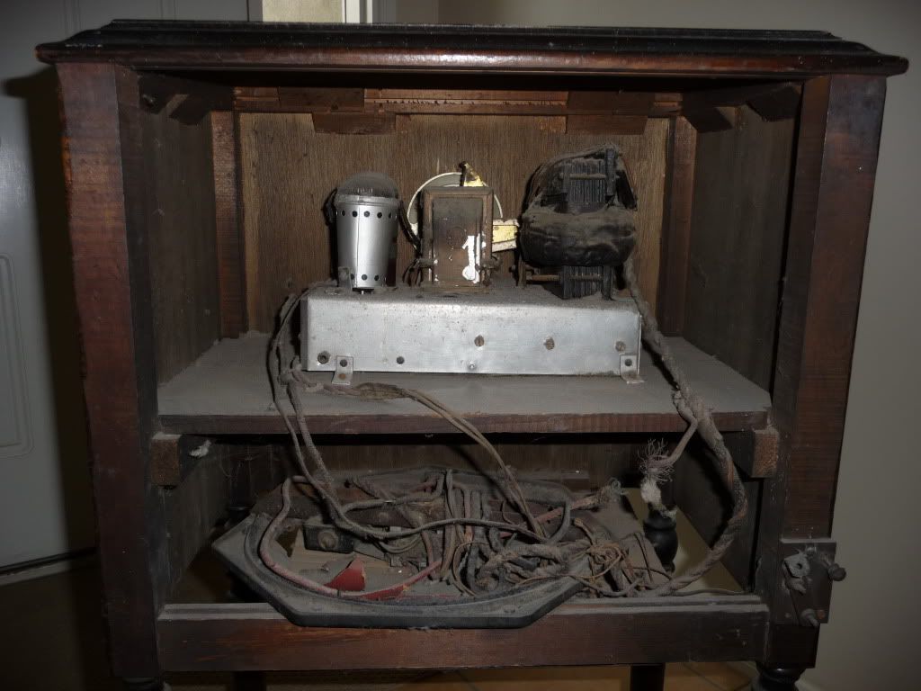
Going by the construction of the large transformer and the bends and brackets on the chassis, is this possibly a home made set? |
|
|
Return to top of page · Post #: 4 · Written at 3:19:44 PM on 17 July 2011.
|
|
|
|
Location: Benalla, VIC
Member since 2 June 2011 Member #: 915 Postcount: 9 |
|
Closest I found by cabinet design..very close to early Stromberg Carlson, chassis unknown... I would say a bitsa!! |
|
|
Return to top of page · Post #: 5 · Written at 6:48:25 PM on 17 July 2011.
|
|
|
|
Location: Wangaratta, VIC
Member since 21 February 2009 Member #: 438 Postcount: 5724 |
|
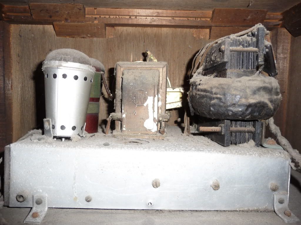
Would agree with the Bitsa. The valves appear to be of early construction, hence request for number. |
|
|
Return to top of page · Post #: 6 · Written at 7:37:49 PM on 17 July 2011.
|
|
|
|
Location: Benalla, VIC
Member since 2 June 2011 Member #: 915 Postcount: 9 |
|
Definitely a re-fit Marc, It seems the original chassis has been discarded at some stage for unknown reasons...burnout maybe? and have recreated their own make although not that good, commercial it isnt....notice the screen grid (excutcheon) is out of allignment from the front view and their appears to be no provision for a speaker...which leads me to believe a external was used? |
|
|
Return to top of page · Post #: 7 · Written at 8:00:45 PM on 18 July 2011.
|
|
|
|
Location: Wangaratta, VIC
Member since 21 February 2009 Member #: 438 Postcount: 5724 |
|
I would suggest that there is insufficient room for a speaker in that cabinet. |
|
|
Return to top of page · Post #: 8 · Written at 9:41:19 PM on 18 July 2011.
|
|
|
|
Location: NSW
Member since 10 June 2010 Member #: 681 Postcount: 1408 |
|
Moving armature speakers were mounted horizontally in some early radios eg an early Philips radio that I cannot immediately give a modlel name or number. Perhaps this was the same. |
|
|
Return to top of page · Post #: 9 · Written at 10:28:41 PM on 18 July 2011.
|
|
|
|
Location: Wangaratta, VIC
Member since 21 February 2009 Member #: 438 Postcount: 5724 |
|
The cabinets blocks appear to have been re-glued carelessly. |
|
|
Return to top of page · Post #: 10 · Written at 10:45:16 AM on 19 July 2011.
|
|
|
|
Location: Blue Mountains, NSW
Member since 30 June 2011 Member #: 944 Postcount: 30 |
|
Homemade regenerative set using first generation of AC valves. Ca. 1929/1930. Even the power transformer is homemade. |
|
|
Return to top of page · Post #: 11 · Written at 12:25:44 PM on 19 July 2011.
|
|
|
|
Location: Wangaratta, VIC
Member since 21 February 2009 Member #: 438 Postcount: 5724 |
|
I don't find two windings unusual. I have repaired a couple of sets of late where they only had on winding for tuning & the other for regeneration. |
|
|
Return to top of page · Post #: 12 · Written at 3:36:36 PM on 19 July 2011.
|
|
|
|
Location: Blue Mountains, NSW
Member since 30 June 2011 Member #: 944 Postcount: 30 |
|
I would have thought the chunky transformer on the side of the chassis was a mains power transformer. If so then valves like UX201 and Philips A series are totally unsuitable as these are directly heated battery valves. |
|
|
Return to top of page · Post #: 13 · Written at 8:36:48 PM on 19 July 2011.
|
|
|
|
Location: Wangaratta, VIC
Member since 21 February 2009 Member #: 438 Postcount: 5724 |
|
The Lyric (TRF) used two 27's and the 26's, 80 and 50 filament tubes were all run on AC... No hum. |
|
|
« Back ·
1 ·
Next »
|
|
|
You need to be a member to post comments on this forum.
|
|
Sign In
Vintage Radio and Television is proudly brought to you by an era where things were built with pride and made to last.
DISCLAIMER: Valve radios and televisions contain voltages that can deliver lethal shocks. You should not attempt to work on a valve radio or other electrical appliances unless you know exactly what you are doing and have gained some experience with electronics and working around high voltages. The owner, administrators and staff of Vintage Radio & Television will accept no liability for any damage, injury or loss of life that comes as a result of your use or mis-use of information on this website. Please read our Safety Warning before using this website.
WARNING: Under no circumstances should you ever apply power to a vintage radio, television or other electrical appliance you have acquired without first having it checked and serviced by an experienced person. Also, at no time should any appliance be connected to an electricity supply if the power cord is damaged. If in doubt, do not apply power.
Shintara - Keepin' It Real · VileSilencer - Maintain The Rage