
General Discussion
Forum home - Go back to General discussion
|
Kriesler 11 38
|
|
|
Return to top of page · Post #: 1 · Written at 7:43:45 PM on 7 November 2025.
|
|
|
|
Location: Sydney, NSW
Member since 1 October 2025 Member #: 2742 Postcount: 40 |
|
I have a Kriesler 11 series radio that I am trying to restore. After much searching and help from people on here (see the Tech Talk forum Kriesler 11-20). I am pretty sure the model I have is an 11-38. It has the identical tube compliment to mine and is a 2 band radio same as mine. It looks like the only 2 band 11 series set with that particular tube layout. 6AN7,6AD8,6M5 and6V4. I have searched long and hard but cannot locate a schematic. If you happen to have the schematic or the service data sheet for this set I would be ever grateful for a copy. My email is unhidden. 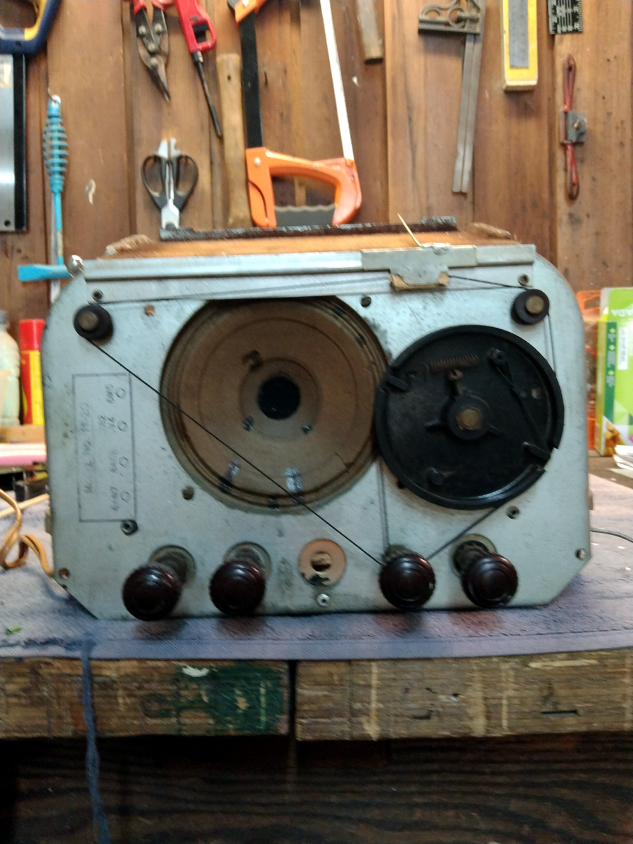 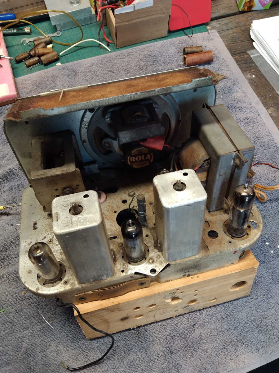 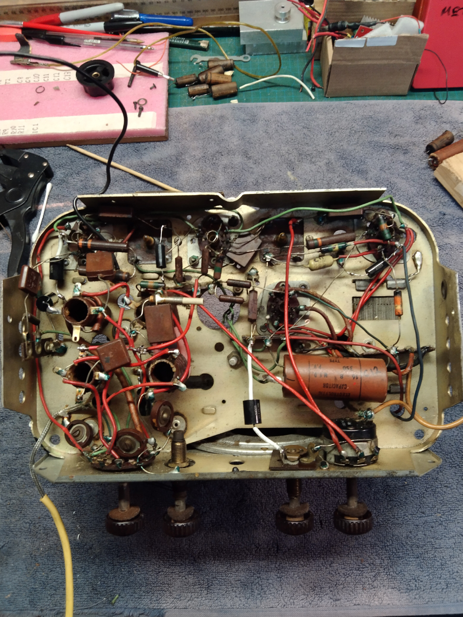 |
|
|
Return to top of page · Post #: 2 · Written at 7:02:02 AM on 8 November 2025.
|
|
|
|
Location: Belrose, NSW
Member since 31 December 2015 Member #: 1844 Postcount: 2687 |
|
This is the single band version |
|
|
Return to top of page · Post #: 3 · Written at 10:09:33 AM on 8 November 2025.
|
|

|
Location: Melbourne, VIC
Member since 20 September 2011 Member #: 1009 Postcount: 1262 |
|
Ray, |
|
|
Return to top of page · Post #: 4 · Written at 11:28:56 AM on 8 November 2025.
|
|
|
|
Location: Sydney, NSW
Member since 1 October 2025 Member #: 2742 Postcount: 40 |
|
Thanks Ian and Mono. I have had a schematic sent to me by GTC and I am pretty sure this is my set. I have traced all around the rectifier tube using the 11-38 schematic GTC sent and it all checks out. Rather than draw this thread out I will post details on the thread I started for that radio in tech talk. It looks like pics are not encouraged on here so I won't post one. Especially now that I am pretty sure I have the right schematic. I did download the one you suggested Ian and it is quite a bit different to mine. I suspect they simplified the dual electrolytic and complicated giant wire wound resistor I have in my set. Man did that take some time to figure out. But once I saw the correct schematic it now makes sense and at least I can change the capacitor out with some degree of certainty. |
|
|
Return to top of page · Post #: 5 · Written at 9:50:00 PM on 8 November 2025.
|
|

|
Location: Hill Top, NSW
Member since 18 September 2015 Member #: 1801 Postcount: 2239 |
|
It looks like pics are not encouraged on here so I won't post one. |
|
|
Return to top of page · Post #: 6 · Written at 1:45:42 AM on 9 November 2025.
|
|

|
Location: Sydney, NSW
Member since 28 January 2011 Member #: 823 Postcount: 6929 |
|
It looks like pics are not encouraged on here so I won't post one. |
|
|
Return to top of page · Post #: 7 · Written at 9:04:16 AM on 9 November 2025.
|
|
|
|
Location: Sydney, NSW
Member since 1 October 2025 Member #: 2742 Postcount: 40 |
|
OK I will take a couple of pics and follow the steps to post them. |
|
|
Return to top of page · Post #: 8 · Written at 10:54:44 AM on 9 November 2025.
|
|
|
|
Location: Sydney, NSW
Member since 1 October 2025 Member #: 2742 Postcount: 40 |
|
Pics uploaded to administrator. I am glad I listened to the advice on pics as I have a nagging suspicion this may be an 11 20x. The valve lineup is almost right. The only difference being the rectifier tube. But it is an interchangeable one to the one in my set. Sadly I cannot find a schematic for the x variant. I did find an old post from Marcc detailing how the chassis stamp is not proof of model as they frequently put different models in that chassis without changing the stamp. Anyway I hope this aids in identifying the model. My money is still on the 11 38 but I'm interested to hear of confirmation or not. |
|
|
Return to top of page · Post #: 9 · Written at 3:21:07 PM on 9 November 2025.
|
|

|
Location: Wangaratta, VIC
Member since 21 February 2009 Member #: 438 Postcount: 5678 |
|
I pointed out that it was a range of different chasses that went into a common cabinet. Kriesler cabinet numbering, is never a good guide as to the chassis in it. |
|
|
Return to top of page · Post #: 10 · Written at 3:47:01 PM on 9 November 2025.
|
|
|
|
Location: Sydney, NSW
Member since 1 October 2025 Member #: 2742 Postcount: 40 |
|
Sorry. My mistake. hopefully the pics will shed some light. |
|
|
Return to top of page · Post #: 11 · Written at 3:49:51 PM on 11 November 2025.
|
|

|
Administrator
Location: Naremburn, NSW
Member since 15 November 2005 Member #: 1 Postcount: 7606 |
|
The photos have been received. I will be doing server updates shortly and following that the photos will be uploaded. ‾‾‾‾‾‾‾‾‾‾‾‾‾‾‾‾‾‾‾‾‾‾‾‾‾‾‾‾‾‾‾‾‾‾‾‾‾‾‾‾‾‾‾‾‾‾‾‾‾‾‾‾‾‾‾‾‾‾‾‾‾‾‾‾‾‾‾‾ A valve a day keeps the transistor away... |
|
|
Return to top of page · Post #: 12 · Written at 6:02:39 AM on 13 November 2025.
|
|
|
|
Administrator
Location: Naremburn, NSW
Member since 15 November 2005 Member #: 1 Postcount: 7606 |
|
Photos uploaded. ‾‾‾‾‾‾‾‾‾‾‾‾‾‾‾‾‾‾‾‾‾‾‾‾‾‾‾‾‾‾‾‾‾‾‾‾‾‾‾‾‾‾‾‾‾‾‾‾‾‾‾‾‾‾‾‾‾‾‾‾‾‾‾‾‾‾‾‾ A valve a day keeps the transistor away... |
|
|
Return to top of page · Post #: 13 · Written at 9:23:14 AM on 13 November 2025.
|
|
|
|
Location: Wangaratta, VIC
Member since 21 February 2009 Member #: 438 Postcount: 5678 |
|
Looks like a typical Kriesler, the green paint where its been factory inspected. I always love the tapped resistor topside, in some radios they are alive. |
|
|
Return to top of page · Post #: 14 · Written at 10:29:24 AM on 13 November 2025.
|
|
|
|
Location: Hill Top, NSW
Member since 18 September 2015 Member #: 1801 Postcount: 2239 |
|
The one electro is a double electro, so 2 in 1 (see wires on left side). It's a 16μF and 8μF in one can. |
|
|
Return to top of page · Post #: 15 · Written at 10:44:56 AM on 13 November 2025.
|
|
|
|
Location: Sydney, NSW
Member since 1 October 2025 Member #: 2742 Postcount: 40 |
|
Thanks to Brad for uploading the pics. The pic showing the chassis stamp denoting model and tube compliment did not come out clear and is unreadable unfortunately. It says this set is an 11-20 and has the valve lineup as 6AN7,6AD8,6V4 and 6M5. (Which is what is in the set). So does that mean I have an 11-20? Even though when I do some tracing it does not check out. Or do I have an 11-38 ? The schematic seems to check out for the 11-38 with a small difference around that big topside resistor which is still confusing the heck out of me. So I am proceeding as if it is an 11 38. |
|
|
You need to be a member to post comments on this forum.
|
|
Sign In
Vintage Radio and Television is proudly brought to you by an era where things were built with pride and made to last.
DISCLAIMER: Valve radios and televisions contain voltages that can deliver lethal shocks. You should not attempt to work on a valve radio or other electrical appliances unless you know exactly what you are doing and have gained some experience with electronics and working around high voltages. The owner, administrators and staff of Vintage Radio & Television will accept no liability for any damage, injury or loss of life that comes as a result of your use or mis-use of information on this website. Please read our Safety Warning before using this website.
WARNING: Under no circumstances should you ever apply power to a vintage radio, television or other electrical appliance you have acquired without first having it checked and serviced by an experienced person. Also, at no time should any appliance be connected to an electricity supply if the power cord is damaged. If in doubt, do not apply power.
Shintara - Keepin' It Real · VileSilencer - Maintain The Rage