
General Discussion
Forum home - Go back to General discussion
|
Mullard MAS 1113-X power transformer replacement questions.
|
|
|
« Back ·
1 ·
Next »
|
|
|
Return to top of page · Post #: 1 · Written at 3:48:51 PM on 12 July 2025.
|
|
|
|
Location: Corlette, NSW
Member since 29 December 2024 Member #: 2695 Postcount: 26 |
|
Hi all. Recently I bought a Mullard, which was sold as a MAS-1110, but since I found it's a Mullard MAS-1113-X SW/BC. 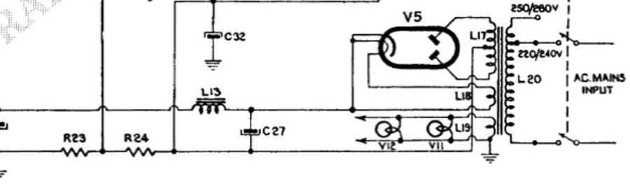 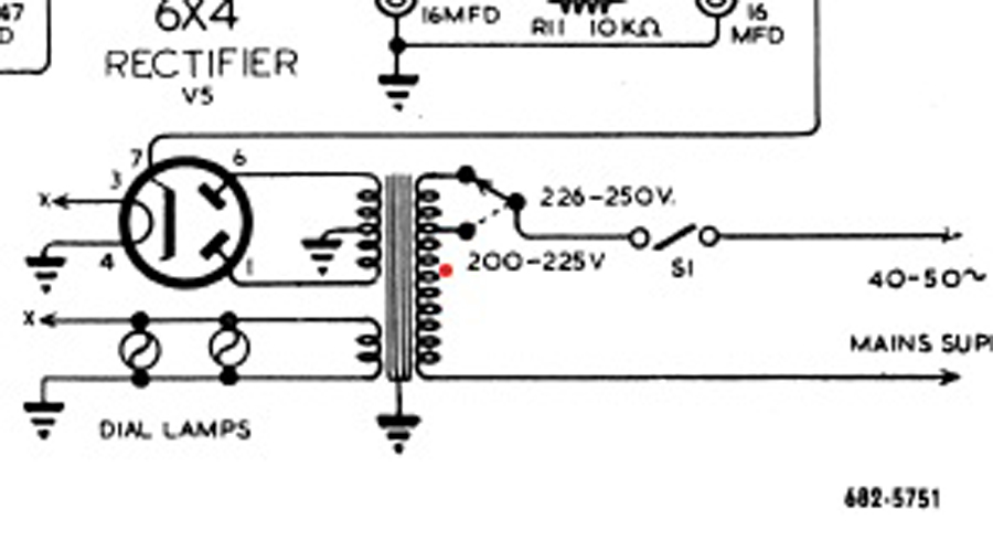 |
|
|
Return to top of page · Post #: 2 · Written at 7:42:45 PM on 12 July 2025.
|
|

|
Location: Hill Top, NSW
Member since 18 September 2015 Member #: 1801 Postcount: 2231 |
|
The heater of the 6V4 should be wired on pins 4 and 5, in parallel with the heater circuit for the rest of the radio. Don't connect the heater to any other pins. |
|
|
Return to top of page · Post #: 3 · Written at 9:30:48 PM on 12 July 2025.
|
|

|
Location: Wangaratta, VIC
Member since 21 February 2009 Member #: 438 Postcount: 5650 |
|
I would expect the transformer to be salvage from a set with a 5Y3, or similar filament rectifier. That would have a 5V winding, 6.3V winding and a centre tapped HT winding. With a 6V4 the 5V winding would be superfluous and not needed. There may be a wire with seemingly no owner and open circuit? If so that is a shielded trans former & it goes to ground. |
|
|
Return to top of page · Post #: 4 · Written at 8:32:04 PM on 13 July 2025.
|
|

|
Administrator
Location: Naremburn, NSW
Member since 15 November 2005 Member #: 1 Postcount: 7580 |
|
Documents uploaded. ‾‾‾‾‾‾‾‾‾‾‾‾‾‾‾‾‾‾‾‾‾‾‾‾‾‾‾‾‾‾‾‾‾‾‾‾‾‾‾‾‾‾‾‾‾‾‾‾‾‾‾‾‾‾‾‾‾‾‾‾‾‾‾‾‾‾‾‾ A valve a day keeps the transistor away... |
|
|
Return to top of page · Post #: 5 · Written at 10:48:34 PM on 13 July 2025.
|
|
|
|
Location: Wangaratta, VIC
Member since 21 February 2009 Member #: 438 Postcount: 5650 |
|
Not quite sure what they were up to here with EZ82, it seems to have only been manufacture here. |
|
|
Return to top of page · Post #: 6 · Written at 4:13:32 PM on 14 July 2025.
|
|
|
|
Location: Hill Top, NSW
Member since 18 September 2015 Member #: 1801 Postcount: 2231 |
|
Ah yes I remember the EZ82 being used with the heater connected to the cathode, which I supposed was to stop the possibility of the cathode shorting out like the early 6X5 was prone to do. |
|
|
Return to top of page · Post #: 7 · Written at 5:29:16 PM on 14 July 2025.
|
|
|
|
Location: Corlette, NSW
Member since 29 December 2024 Member #: 2695 Postcount: 26 |
|
Hi Robbbert. Thanks for the email reply and explanation. |
|
|
Return to top of page · Post #: 8 · Written at 8:36:10 PM on 14 July 2025.
|
|
|
|
Location: Belrose, NSW
Member since 31 December 2015 Member #: 1844 Postcount: 2666 |
|
If you use a 6V4 and not an EZ82 there should be no problem wiring it like the 6X4 circuit. But using pins 4 and 5 for the heater, of course. |
|
|
Return to top of page · Post #: 9 · Written at 10:25:39 PM on 14 July 2025.
|
|
|
|
Location: Wangaratta, VIC
Member since 21 February 2009 Member #: 438 Postcount: 5650 |
|
As an aside: The Russians have made a ruggedised 5Y3 similar to the 6V4 etc. With what is not dissimilar to the shape of a tank stand with on up and one down. I strongly suspect there is a cathode sleeve as there is no surge, but the filament is a rod around 4mm in diameter. That seems to cure the issue of the sagging heater strip in a tube, shorting in all but one position. |
|
|
Return to top of page · Post #: 10 · Written at 10:57:58 AM on 15 July 2025.
|
|
|
|
Location: Corlette, NSW
Member since 29 December 2024 Member #: 2695 Postcount: 26 |
|
Hi all. Sorry to be a pain and I appreciate your patients. I think the replies are missing the what I have asked therefore, just to clarify the help I need. |
|
|
Return to top of page · Post #: 11 · Written at 3:23:10 PM on 15 July 2025.
|
|
|
|
Location: Hill Top, NSW
Member since 18 September 2015 Member #: 1801 Postcount: 2231 |
|
can I wire the existing transformer to suit the MAS 1113-X radios circuitry. |
|
|
Return to top of page · Post #: 12 · Written at 6:58:18 PM on 15 July 2025.
|
|
|
|
Location: Belrose, NSW
Member since 31 December 2015 Member #: 1844 Postcount: 2666 |
|
Vintage User, it seems you are missing something because your questions have already been answered, more than once. |
|
|
Return to top of page · Post #: 13 · Written at 12:39:48 PM on 18 July 2025.
|
|
|
|
Location: Corlette, NSW
Member since 29 December 2024 Member #: 2695 Postcount: 26 |
|
Hi Ian. |
|
|
« Back ·
1 ·
Next »
|
|
|
You need to be a member to post comments on this forum.
|
|
Sign In
Vintage Radio and Television is proudly brought to you by an era where things were built with pride and made to last.
DISCLAIMER: Valve radios and televisions contain voltages that can deliver lethal shocks. You should not attempt to work on a valve radio or other electrical appliances unless you know exactly what you are doing and have gained some experience with electronics and working around high voltages. The owner, administrators and staff of Vintage Radio & Television will accept no liability for any damage, injury or loss of life that comes as a result of your use or mis-use of information on this website. Please read our Safety Warning before using this website.
WARNING: Under no circumstances should you ever apply power to a vintage radio, television or other electrical appliance you have acquired without first having it checked and serviced by an experienced person. Also, at no time should any appliance be connected to an electricity supply if the power cord is damaged. If in doubt, do not apply power.
Shintara - Keepin' It Real · VileSilencer - Maintain The Rage