
General Discussion
Forum home - Go back to General discussion
|
Salonola Radio.
|
|
|
Return to top of page · Post #: 1 · Written at 10:30:55 PM on 16 January 2025.
|
|

|
Location: Latham, ACT
Member since 21 February 2015 Member #: 1705 Postcount: 2221 |
|
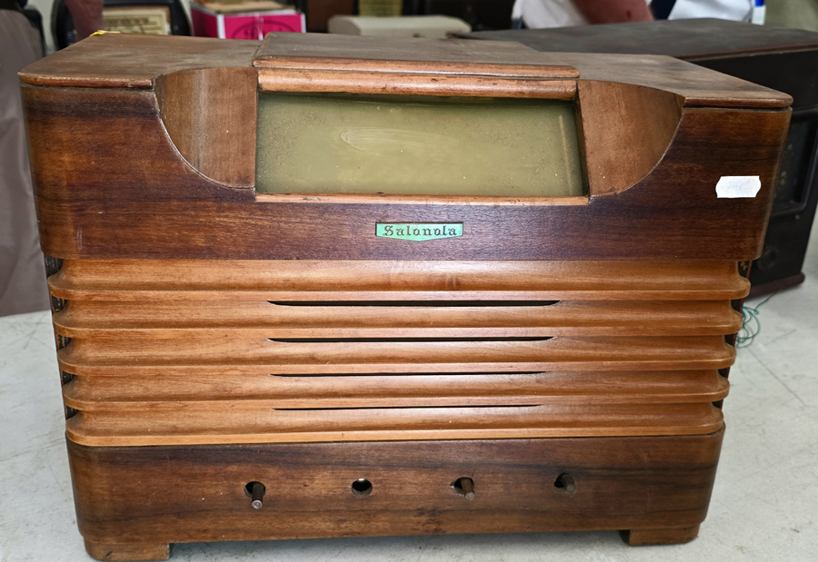
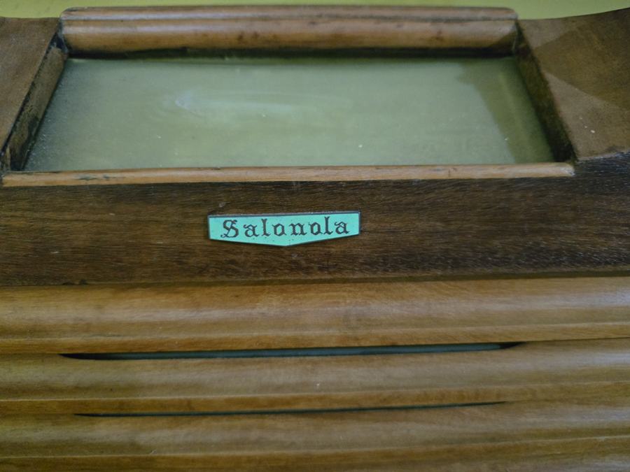
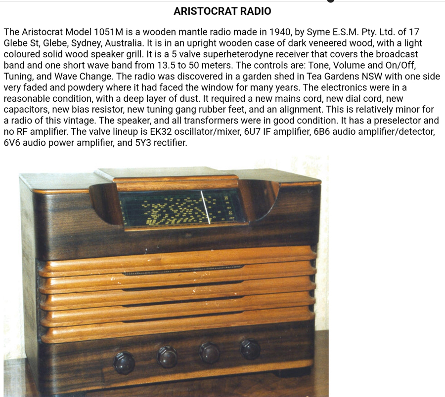
I recently picked up a really unique Salonola Wooden cabinet radio at the ACT HRSA meet 2 weeks ago. My uneducated Guess was it was French or European but no no no it's Aussie and made in Sydney. It's a direct copy of a Aristocrat Model 1051M . The valve line up is EK32, 6U7, 6B6, 6V6 & 5Y3. It's a really lovely example. The one issue I know of is the volume/on/off switch shaft is snapped ( how does that happen lol). I have a big EKCO on my restoring bench at the moment but this one is next. Will send photos to Brad . |
|
|
Return to top of page · Post #: 2 · Written at 5:19:20 AM on 19 January 2025.
|
|
|
|
Location: Latham, ACT
Member since 21 February 2015 Member #: 1705 Postcount: 2221 |
    |
|
|
Return to top of page · Post #: 3 · Written at 10:29:48 PM on 20 January 2025.
|
|
|
|
Location: Sydney, NSW
Member since 11 July 2024 Member #: 2656 Postcount: 21 |
|
Hi Carl, I have a Salonola radio with a Breville chassis & 8" speaker, the console still needs a resto, radio works & sound great. Wonder if it's the same as yours? |
|
|
Return to top of page · Post #: 4 · Written at 1:48:55 AM on 21 January 2025.
|
|
|
|
Location: Latham, ACT
Member since 21 February 2015 Member #: 1705 Postcount: 2221 |
|
Hi Darrinh mine is a mantle/table radio. The photos should be up soon. |
|
|
Return to top of page · Post #: 5 · Written at 5:51:06 AM on 21 January 2025.
|
|

|
Administrator
Location: Naremburn, NSW
Member since 15 November 2005 Member #: 1 Postcount: 7606 |
|
Photos uploaded to Post 2. ‾‾‾‾‾‾‾‾‾‾‾‾‾‾‾‾‾‾‾‾‾‾‾‾‾‾‾‾‾‾‾‾‾‾‾‾‾‾‾‾‾‾‾‾‾‾‾‾‾‾‾‾‾‾‾‾‾‾‾‾‾‾‾‾‾‾‾‾ A valve a day keeps the transistor away... |
|
|
Return to top of page · Post #: 6 · Written at 8:50:12 PM on 21 January 2025.
|
|
|
|
Location: Latham, ACT
Member since 21 February 2015 Member #: 1705 Postcount: 2221 |
|
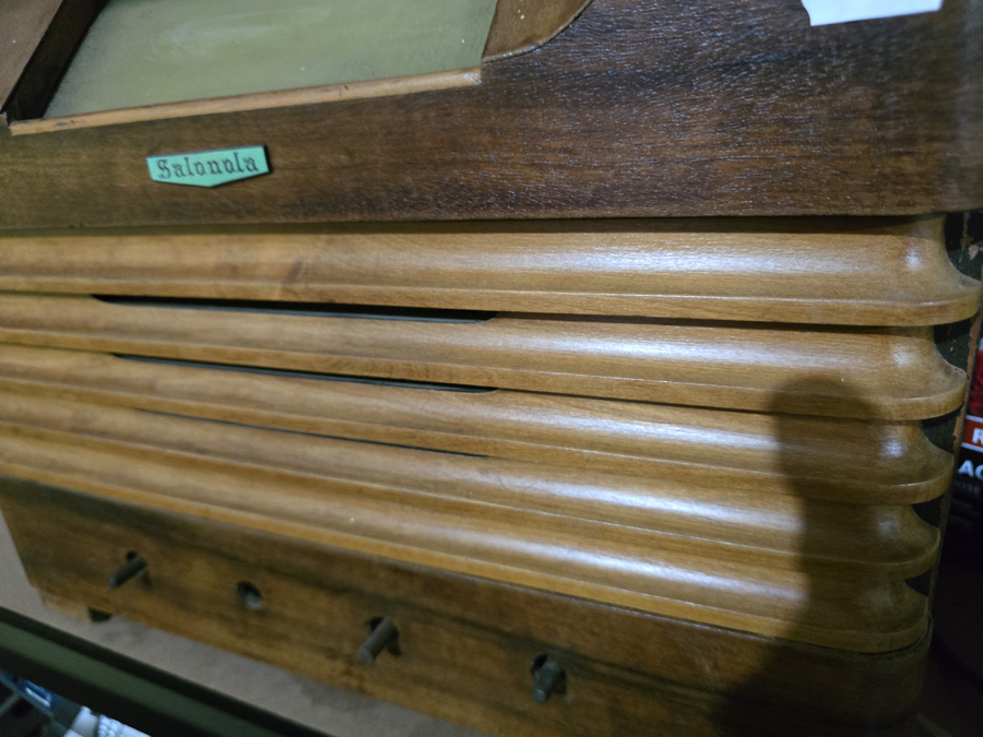
Thankyou Brad. As you can see the cabinet is near pristine. Will be getting into it soon. |
|
|
Return to top of page · Post #: 7 · Written at 10:01:17 AM on 25 January 2025.
|
|
|
|
Location: Latham, ACT
Member since 21 February 2015 Member #: 1705 Postcount: 2221 |
|
Wow this set works but boy has it been bodgied up. It needs everything. A good clean and more deteriorating wires. The speaker wire is threadbare rubber coated but the field coil wires in the same harness is cotton covered! What gives? Anyway it's certainly fixable. |
|
|
Return to top of page · Post #: 8 · Written at 8:45:11 PM on 28 January 2025.
|
|
|
|
Location: Latham, ACT
Member since 21 February 2015 Member #: 1705 Postcount: 2221 |
|
Well I had to stay up and wait for some parcels this morning so I spent 40 minutes recapping and replacing crumbling wires. Am sending another photo to Brad as I have some questions for you guys. It performs very well but can be better. 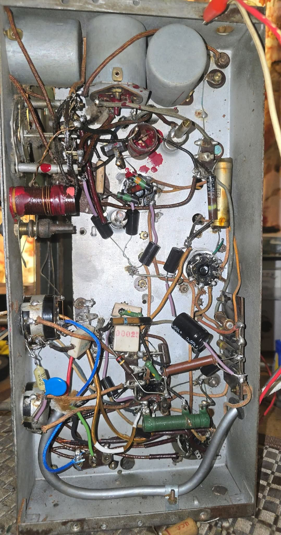 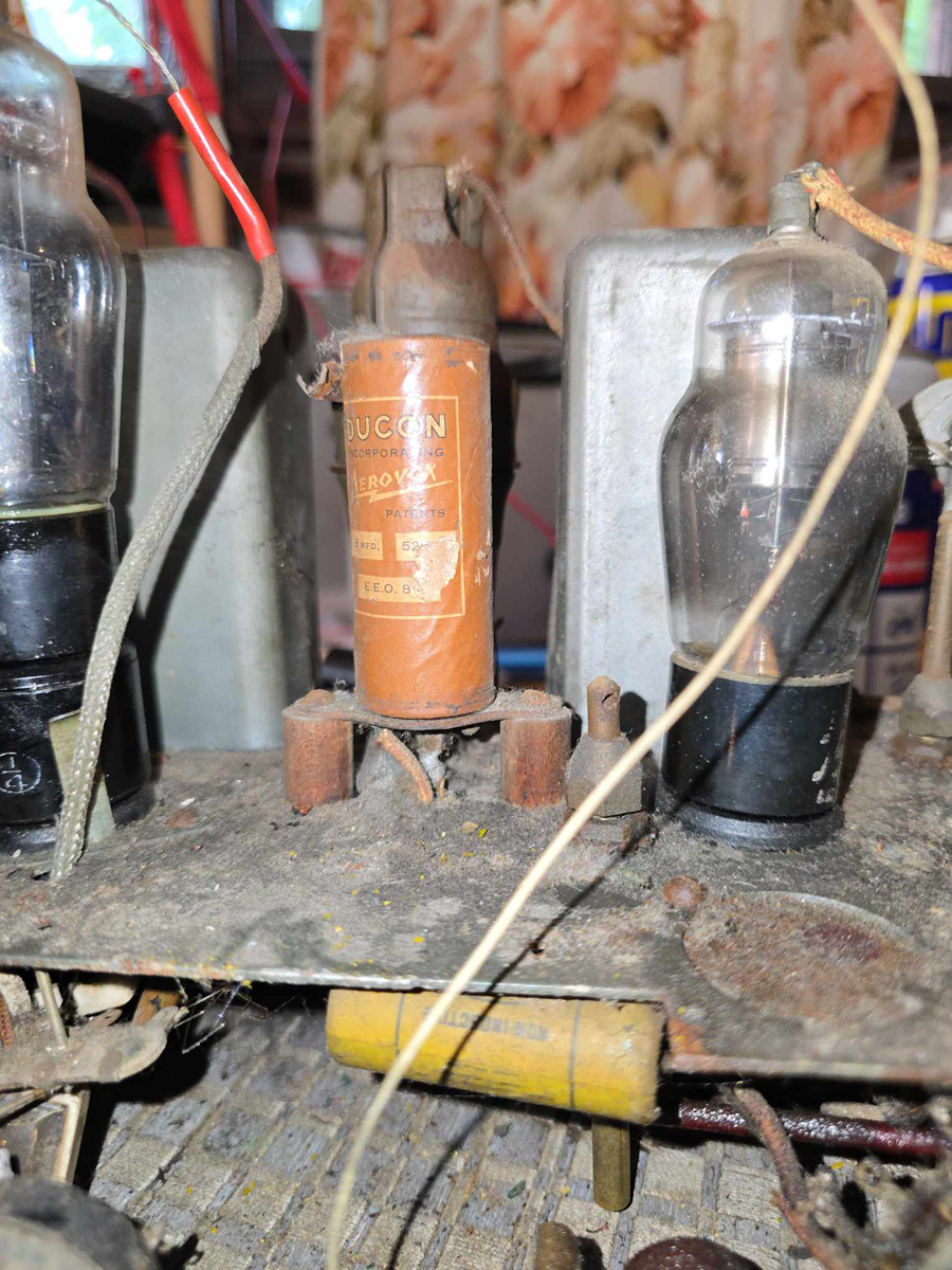 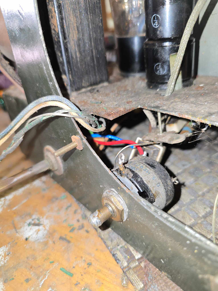 |
|
|
Return to top of page · Post #: 9 · Written at 11:58:15 AM on 1 February 2025.
|
|
|
|
Administrator
Location: Naremburn, NSW
Member since 15 November 2005 Member #: 1 Postcount: 7606 |
|
Photos uploaded to Post 8. ‾‾‾‾‾‾‾‾‾‾‾‾‾‾‾‾‾‾‾‾‾‾‾‾‾‾‾‾‾‾‾‾‾‾‾‾‾‾‾‾‾‾‾‾‾‾‾‾‾‾‾‾‾‾‾‾‾‾‾‾‾‾‾‾‾‾‾‾ A valve a day keeps the transistor away... |
|
|
Return to top of page · Post #: 10 · Written at 2:20:18 AM on 2 February 2025.
|
|
|
|
Location: Latham, ACT
Member since 21 February 2015 Member #: 1705 Postcount: 2221 |
|
Thankyou Brad. |
|
|
Return to top of page · Post #: 11 · Written at 3:05:26 AM on 2 February 2025.
|
|

|
Location: Hill Top, NSW
Member since 18 September 2015 Member #: 1801 Postcount: 2239 |
|
Why replace it if it's working? |
|
|
Return to top of page · Post #: 12 · Written at 9:06:36 AM on 2 February 2025.
|
|
|
|
Location: Latham, ACT
Member since 21 February 2015 Member #: 1705 Postcount: 2221 |
|
Robbert it's corroded and I don't think the 30 ohm section is connected properly or at all when it's running. |
|
|
Return to top of page · Post #: 13 · Written at 1:55:24 PM on 2 February 2025.
|
|
|
|
Location: NSW
Member since 10 June 2010 Member #: 681 Postcount: 1395 |
|
At a guess the w/w resistor is for setting the cathode bias of RF/IF valves. So it would be carrying a lot of the current flowing through a number of valves and as Robbbert says should be maybe 5watt. |
|
|
Return to top of page · Post #: 14 · Written at 10:55:35 PM on 2 February 2025.
|
|

|
Location: Wangaratta, VIC
Member since 21 February 2009 Member #: 438 Postcount: 5678 |
|
One can clearly see the 8mfd cap is above ground, which means its negative is on the Centre tap, which further means that the 30 ohm resistor is "Back Bias" or part of it. |
|
|
Return to top of page · Post #: 15 · Written at 8:06:00 PM on 3 February 2025.
|
|
|
|
Location: Belrose, NSW
Member since 31 December 2015 Member #: 1844 Postcount: 2687 |
|
You can easily work out the value of the back-bias resistor. |
|
|
You need to be a member to post comments on this forum.
|
|
 250V plate for 6V6. Chassis positive in respect to CT. The back bias voltage is dependant on the cathode current of all tubes as all of it goes to ground via it. Therefore it is a diagnostic. Resistor
 Sign In
Vintage Radio and Television is proudly brought to you by an era where things were built with pride and made to last.
DISCLAIMER: Valve radios and televisions contain voltages that can deliver lethal shocks. You should not attempt to work on a valve radio or other electrical appliances unless you know exactly what you are doing and have gained some experience with electronics and working around high voltages. The owner, administrators and staff of Vintage Radio & Television will accept no liability for any damage, injury or loss of life that comes as a result of your use or mis-use of information on this website. Please read our Safety Warning before using this website.
WARNING: Under no circumstances should you ever apply power to a vintage radio, television or other electrical appliance you have acquired without first having it checked and serviced by an experienced person. Also, at no time should any appliance be connected to an electricity supply if the power cord is damaged. If in doubt, do not apply power.
Shintara - Keepin' It Real · VileSilencer - Maintain The Rage