General Discussion
Forum home - Go back to General discussion
|
Airplayer radio
|
|
|
Return to top of page · Post #: 1 · Written at 5:04:23 PM on 16 August 2024.
|
|
|
|
Location: Two Wells, SA
Member since 16 August 2024 Member #: 2672 Postcount: 33 |
|
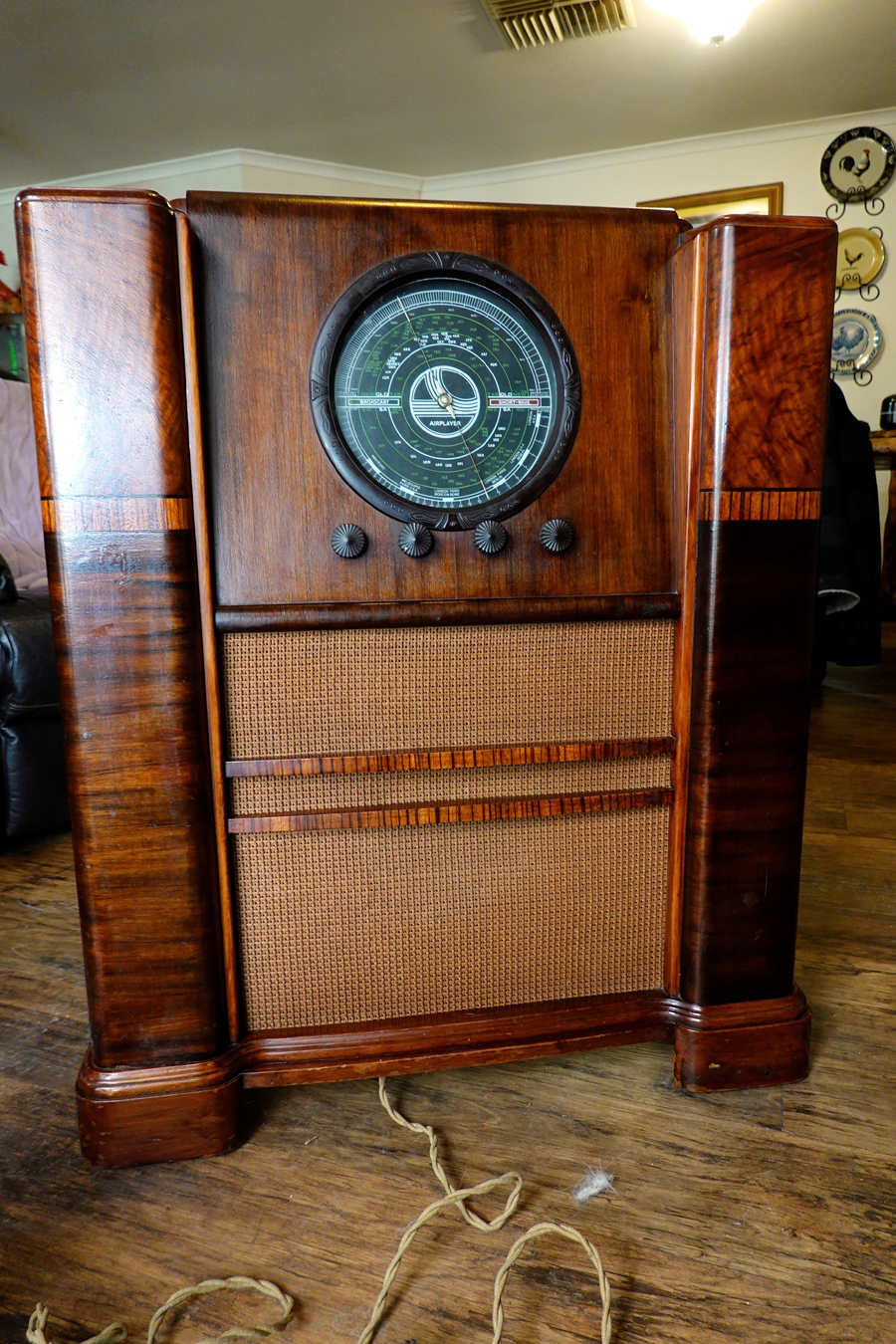
Hi all I have just joined your forum and looking for info and schematics on a radio I have.   |
|
|
Return to top of page · Post #: 2 · Written at 7:03:03 PM on 16 August 2024.
|
|
|
|
Location: Sydney, NSW
Member since 28 January 2011 Member #: 823 Postcount: 6929 |
|
Do you mean EK2? |
|
|
Return to top of page · Post #: 3 · Written at 7:14:30 PM on 16 August 2024.
|
|
|
|
Location: Two Wells, SA
Member since 16 August 2024 Member #: 2672 Postcount: 33 |
|
It's a on floor console, I have added pictures but not yet accepted on forum |
|
|
Return to top of page · Post #: 4 · Written at 8:14:41 PM on 16 August 2024.
|
|
|
|
Location: Hill Top, NSW
Member since 18 September 2015 Member #: 1801 Postcount: 2239 |
|
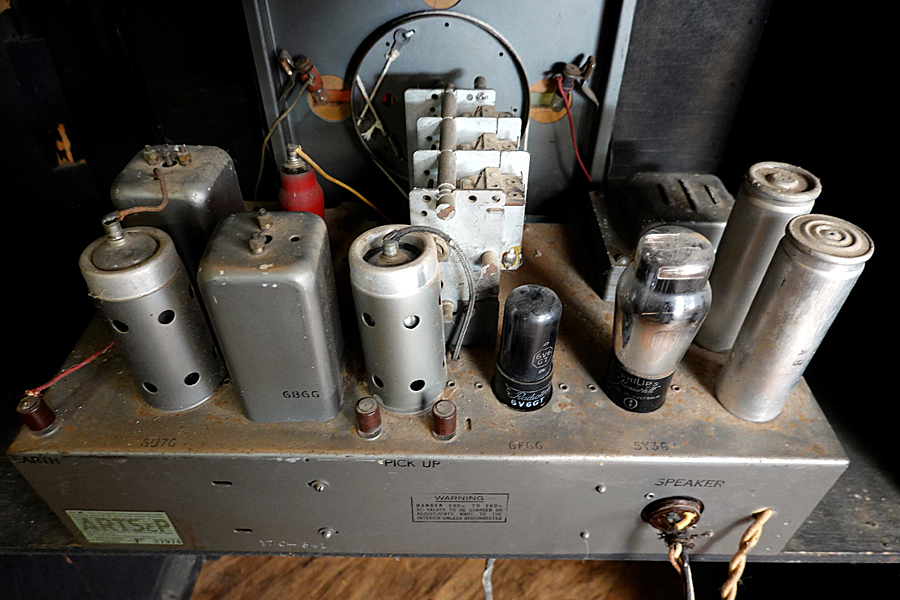
EK2 has the unpopular Philips base, it was replaced by the EK32 (or EK2G) with octal base. The EK2G has gold paint. I'd say the EK32 will be correct. |
|
|
Return to top of page · Post #: 5 · Written at 9:14:37 PM on 16 August 2024.
|
|
|
|
Location: Belrose, NSW
Member since 31 December 2015 Member #: 1844 Postcount: 2687 |
|
Airplayer was a Philips moniker.... |
|
|
Return to top of page · Post #: 6 · Written at 10:50:16 PM on 16 August 2024.
|
|
|
|
Location: Wangaratta, VIC
Member since 21 February 2009 Member #: 438 Postcount: 5678 |
|
Only one I see is 3052B with that frequency changer; however, it has 6F6 meaning 6V6 may be wrong? Being 1945 there was a lot of chopping & changing of tubes in wartime. That did include reverting to older 6pin tubes. |
|
|
Return to top of page · Post #: 7 · Written at 12:21:17 AM on 17 August 2024.
|
|
|
|
Location: Hill Top, NSW
Member since 18 September 2015 Member #: 1801 Postcount: 2239 |
|
6F6 and 6V6 are pin-compatible output valves, however the specs are different. Still close enough to work though. |
|
|
Return to top of page · Post #: 8 · Written at 6:55:42 AM on 17 August 2024.
|
|
|
|
Administrator
Location: Naremburn, NSW
Member since 15 November 2005 Member #: 1 Postcount: 7606 |
|
Photos uploaded. ‾‾‾‾‾‾‾‾‾‾‾‾‾‾‾‾‾‾‾‾‾‾‾‾‾‾‾‾‾‾‾‾‾‾‾‾‾‾‾‾‾‾‾‾‾‾‾‾‾‾‾‾‾‾‾‾‾‾‾‾‾‾‾‾‾‾‾‾ A valve a day keeps the transistor away... |
|
|
Return to top of page · Post #: 9 · Written at 7:23:11 AM on 17 August 2024.
|
|
|
|
Location: Toongabbie, NSW
Member since 19 November 2015 Member #: 1828 Postcount: 1397 |
|
Hi Johnny, that's a very nice original looking radio. |
|
|
Return to top of page · Post #: 10 · Written at 8:44:05 AM on 17 August 2024.
|
|
|
|
Location: Belrose, NSW
Member since 31 December 2015 Member #: 1844 Postcount: 2687 |
|
"The electrolytics may be original and may explode if suddenly powered up, may need replacing." |
|
|
Return to top of page · Post #: 11 · Written at 10:37:17 AM on 17 August 2024.
|
|
|
|
Location: Two Wells, SA
Member since 16 August 2024 Member #: 2672 Postcount: 33 |
|
Thanks for the info, I also suspect its made by Breville but not sure. |
|
|
Return to top of page · Post #: 12 · Written at 10:52:45 AM on 17 August 2024.
|
|
|
|
Location: Wangaratta, VIC
Member since 21 February 2009 Member #: 438 Postcount: 5678 |
|
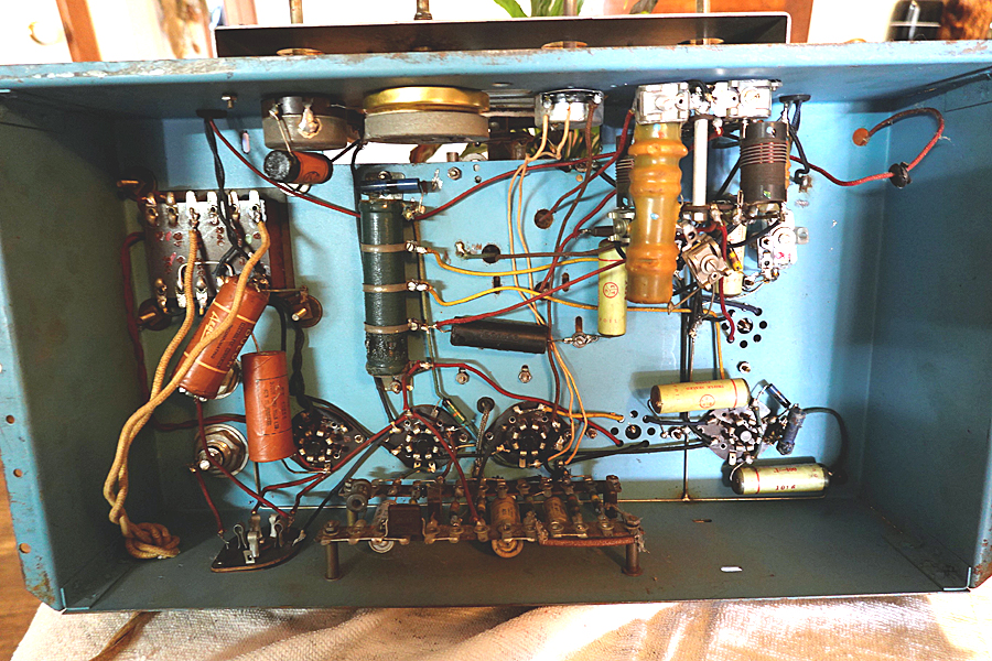
It might be time to slip the chassis. Some sets do have the number on the front of the chassis, or on a corner at the top. |
|
|
Return to top of page · Post #: 13 · Written at 1:19:42 PM on 17 August 2024.
|
|
|
|
Location: Hill Top, NSW
Member since 18 September 2015 Member #: 1801 Postcount: 2239 |
|
Yes, a lovely radio to look at. |
|
|
Return to top of page · Post #: 14 · Written at 1:27:23 PM on 17 August 2024.
|
|
|
|
Location: Two Wells, SA
Member since 16 August 2024 Member #: 2672 Postcount: 33 |
|
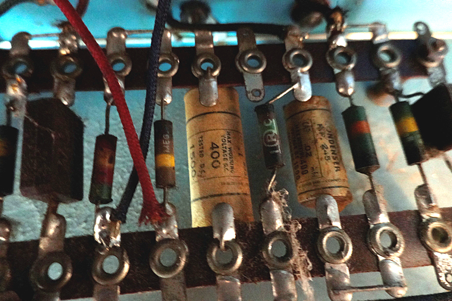
Thanks for replies... Ok, I have added pics of the under chassis, just waiting for them to be put up.   |
|
|
Return to top of page · Post #: 15 · Written at 3:43:04 PM on 17 August 2024.
|
|
|
|
Location: Belrose, NSW
Member since 31 December 2015 Member #: 1844 Postcount: 2687 |
|
A fuse is always a good idea, but be aware that it's not an ideal way to protect the radio. |
|
|
You need to be a member to post comments on this forum.
|
|

Sign In

Vintage Radio and Television is proudly brought to you by an era where things were built with pride and made to last.
DISCLAIMER: Valve radios and televisions contain voltages that can deliver lethal shocks. You should not attempt to work on a valve radio or other electrical appliances unless you know exactly what you are doing and have gained some experience with electronics and working around high voltages. The owner, administrators and staff of Vintage Radio & Television will accept no liability for any damage, injury or loss of life that comes as a result of your use or mis-use of information on this website. Please read our Safety Warning before using this website.
WARNING: Under no circumstances should you ever apply power to a vintage radio, television or other electrical appliance you have acquired without first having it checked and serviced by an experienced person. Also, at no time should any appliance be connected to an electricity supply if the power cord is damaged. If in doubt, do not apply power.
Shintara - Keepin' It Real · VileSilencer - Maintain The Rage
