
General Discussion
Forum home - Go back to General discussion
|
Fixing a friends grandmothers radio need help identifying it
|
|
|
Return to top of page · Post #: 1 · Written at 1:01:47 AM on 11 July 2024.
|
|
|
|
Location: Melb, VIC
Member since 11 July 2024 Member #: 2655 Postcount: 3 |
|
Hi there everyone. 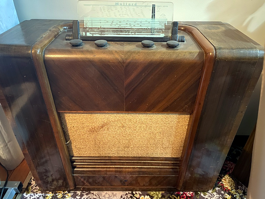 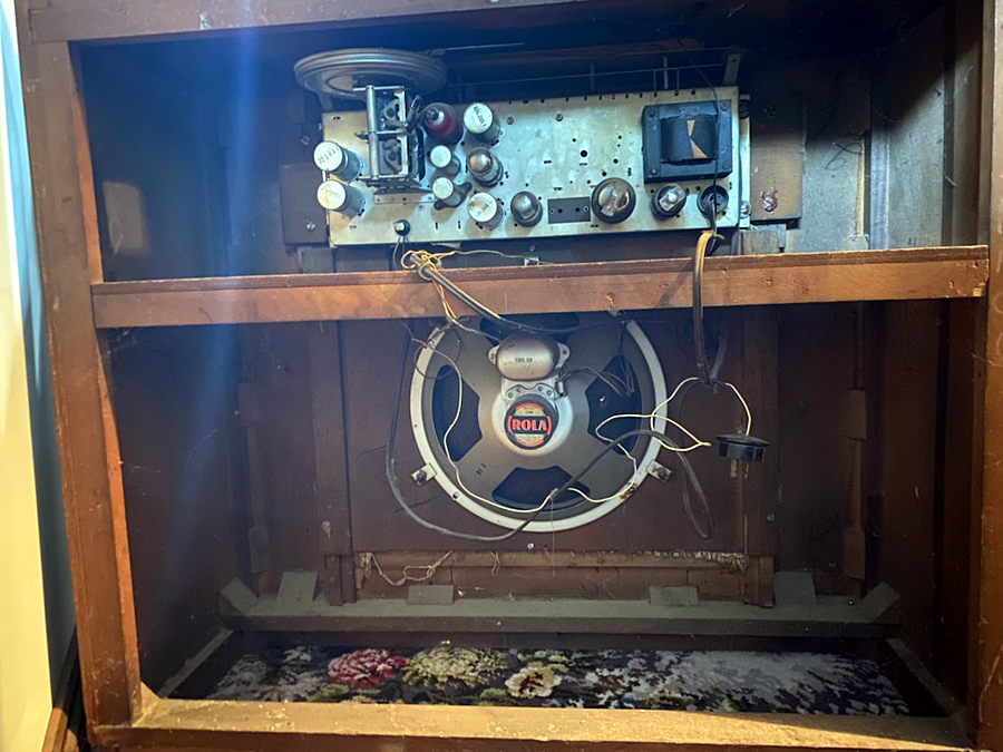 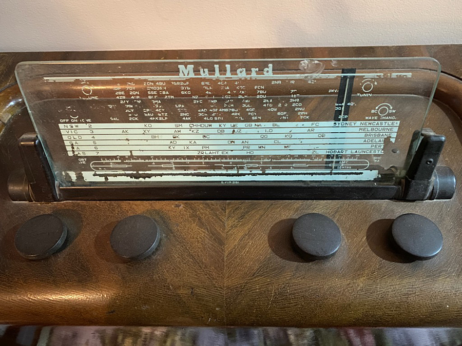 |
|
|
Return to top of page · Post #: 2 · Written at 9:54:15 PM on 11 July 2024.
|
|

|
Location: Wangaratta, VIC
Member since 21 February 2009 Member #: 438 Postcount: 5715 |
|
One will wait & see but plugging it in / powering it to see if it works is not step one. I see the damage & am expected to fix some of it. |
|
|
Return to top of page · Post #: 3 · Written at 5:08:15 AM on 12 July 2024.
|
|

|
Administrator
Location: Naremburn, NSW
Member since 15 November 2005 Member #: 1 Postcount: 7626 |
|
It's a Mullard, manufactured by Philips during the early 1940s. There is a cardboard plaque inside the radio at the back. It may have the model number on it or it may just show valve types and locations and perhaps dial cord information. There may also be a green sticker on the part of the chassis where some wiring comes out (on the side facing the loudspeaker). There is usually a capital letter followed by four or five digits. The letter will give you the year the radio was made. Mullard radios were manufactured by Airzone before WWII so this will most likely be a 40s model. ‾‾‾‾‾‾‾‾‾‾‾‾‾‾‾‾‾‾‾‾‾‾‾‾‾‾‾‾‾‾‾‾‾‾‾‾‾‾‾‾‾‾‾‾‾‾‾‾‾‾‾‾‾‾‾‾‾‾‾‾‾‾‾‾‾‾‾‾ A valve a day keeps the transistor away... |
|
|
Return to top of page · Post #: 4 · Written at 7:11:39 AM on 12 July 2024.
|
|

|
Location: Sydney, NSW
Member since 28 January 2011 Member #: 823 Postcount: 6949 |
|
|
|
|
Return to top of page · Post #: 5 · Written at 7:23:36 PM on 12 July 2024.
|
|
|
|
Location: Belrose, NSW
Member since 31 December 2015 Member #: 1844 Postcount: 2710 |
|
That is a MAS1108. |
|
|
Return to top of page · Post #: 6 · Written at 8:51:59 PM on 12 July 2024.
|
|
|
|
Location: Toongabbie, NSW
Member since 19 November 2015 Member #: 1828 Postcount: 1408 |
|
Hi Rolfred. |
|
|
Return to top of page · Post #: 7 · Written at 10:43:20 PM on 12 July 2024.
|
|
|
|
Location: Melb, VIC
Member since 11 July 2024 Member #: 2655 Postcount: 3 |
|
Thank you to all especially Ian for the link to the schematics. I build valve amps so have experience with do's and donts but I am thankful to all for the hints and cautions..I have not plugged it in and turned it on (I know that much at least).\ |
|
|
Return to top of page · Post #: 8 · Written at 11:41:14 PM on 12 July 2024.
|
|
|
|
Location: Wangaratta, VIC
Member since 21 February 2009 Member #: 438 Postcount: 5715 |
|
Dim bulb is commonly light bulbs in series with the transformer in this case. Aimed at soaking up the load & current limiting, should there be a short or overload. Not a believer in the method. |
|
|
Return to top of page · Post #: 9 · Written at 1:11:19 AM on 13 July 2024.
|
|
|
|
Location: Melb, VIC
Member since 11 July 2024 Member #: 2655 Postcount: 3 |
|
Thanks for the tip on the 16μF caps Marcc |
|
|
Return to top of page · Post #: 10 · Written at 6:22:28 AM on 13 July 2024.
|
|
|
|
Administrator
Location: Naremburn, NSW
Member since 15 November 2005 Member #: 1 Postcount: 7626 |
|
Upon checking, I ran into that Adobe link too. I am not sure what the story is with that but it will aggravate anyone that, like me, just uses their web browser to view PDF files. If there was a way to circumvent it, I wouldn't have an issue but it looks like the button has to be pressed first. ‾‾‾‾‾‾‾‾‾‾‾‾‾‾‾‾‾‾‾‾‾‾‾‾‾‾‾‾‾‾‾‾‾‾‾‾‾‾‾‾‾‾‾‾‾‾‾‾‾‾‾‾‾‾‾‾‾‾‾‾‾‾‾‾‾‾‾‾ A valve a day keeps the transistor away... |
|
|
Return to top of page · Post #: 11 · Written at 10:21:23 AM on 13 July 2024.
|
|
|
|
Location: Belrose, NSW
Member since 31 December 2015 Member #: 1844 Postcount: 2710 |
|
On that site my system (Firefox) won't let you view them in the browser, just download them, which I do to a safe file area. No problem. |
|
|
Return to top of page · Post #: 12 · Written at 5:07:14 PM on 13 July 2024.
|
|

|
Location: Hobart, TAS
Member since 31 July 2016 Member #: 1959 Postcount: 605 |
|
Yes the "dim bulb" tester is one of the really best service tools. |
|
|
Return to top of page · Post #: 13 · Written at 9:41:20 PM on 13 July 2024.
|
|
|
|
Location: Wangaratta, VIC
Member since 21 February 2009 Member #: 438 Postcount: 5715 |
|
That Adobe ambush does them no favours in my book & if I get a pdf file the ABBY Fine Reader can read it. That sort of hijack just totally destroys the usefulness of the site Radio Museum & others are going the same way, obviously they don't want people using their sites. |
|
|
Return to top of page · Post #: 14 · Written at 12:58:18 AM on 14 July 2024.
|
|

|
Location: Hill Top, NSW
Member since 18 September 2015 Member #: 1801 Postcount: 2255 |
|
I had a look at that PDF, and found a way to extract what we want. Firstly I clicked on the link provided by Ian and it downloaded to my hard drive (I have Firefox set up that way). Then I opened the document with Adobe Reader and got a page with F I on it. This indicates that the file contains flash content which is no longer supported by Adobe and they refuse to run it. |
|
|
Return to top of page · Post #: 15 · Written at 8:46:56 AM on 14 July 2024.
|
|
|
|
Location: Hobart, TAS
Member since 31 July 2016 Member #: 1959 Postcount: 605 |
|
A light spay of normal "hair spray" is effective in retaining loose lettering. |
|
|
You need to be a member to post comments on this forum.
|
|
 Rolfred: A list of the valve types is often helpful with identifying the model.
Sign In
Vintage Radio and Television is proudly brought to you by an era where things were built with pride and made to last.
DISCLAIMER: Valve radios and televisions contain voltages that can deliver lethal shocks. You should not attempt to work on a valve radio or other electrical appliances unless you know exactly what you are doing and have gained some experience with electronics and working around high voltages. The owner, administrators and staff of Vintage Radio & Television will accept no liability for any damage, injury or loss of life that comes as a result of your use or mis-use of information on this website. Please read our Safety Warning before using this website.
WARNING: Under no circumstances should you ever apply power to a vintage radio, television or other electrical appliance you have acquired without first having it checked and serviced by an experienced person. Also, at no time should any appliance be connected to an electricity supply if the power cord is damaged. If in doubt, do not apply power.
Shintara - Keepin' It Real · VileSilencer - Maintain The Rage