
General Discussion
Forum home - Go back to General discussion
|
Help please to identify early Holden Radio
|
|
|
Return to top of page · Post #: 16 · Written at 6:42:39 PM on 5 February 2023.
|
|
|
|
Location: Belrose, NSW
Member since 31 December 2015 Member #: 1844 Postcount: 2375 |
|
Your radio was made in 1936. The "C" denotes this. |
|
|
Return to top of page · Post #: 17 · Written at 7:39:42 PM on 5 February 2023.
|
|

|
Location: Melbourne, VIC
Member since 20 September 2011 Member #: 1009 Postcount: 1182 |
|
1936 is a wee bit early for a Model 6395 (CG). The CG was released in 1938 and had push-button tuning. |
|
|
Return to top of page · Post #: 18 · Written at 8:12:57 PM on 5 February 2023.
|
|
|
|
Location: Belrose, NSW
Member since 31 December 2015 Member #: 1844 Postcount: 2375 |
|
The CG is the closest model I can find on Kevin's site. The only difference I guess would be the head unit. |
|
|
Return to top of page · Post #: 19 · Written at 11:39:08 PM on 5 February 2023.
|
|

|
Location: Wangaratta, VIC
Member since 21 February 2009 Member #: 438 Postcount: 5267 |
|
I have sent a couple of photos to Brad of a set here that has lots of similarities. It cannot be before 1933. 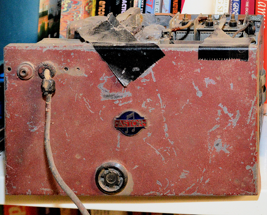 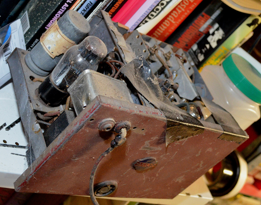 |
|
|
Return to top of page · Post #: 20 · Written at 8:57:05 PM on 6 February 2023.
|
|

|
Administrator
Location: Naremburn, NSW
Member since 15 November 2005 Member #: 1 Postcount: 7311 |
|
Photos uploaded to Post 19. ‾‾‾‾‾‾‾‾‾‾‾‾‾‾‾‾‾‾‾‾‾‾‾‾‾‾‾‾‾‾‾‾‾‾‾‾‾‾‾‾‾‾‾‾‾‾‾‾‾‾‾‾‾‾‾‾‾‾‾‾‾‾‾‾‾‾‾‾ A valve a day keeps the transistor away... |
|
|
Return to top of page · Post #: 21 · Written at 7:39:31 AM on 9 February 2023.
|
|
|
|
Location: Tamworth, NSW
Member since 27 January 2023 Member #: 2536 Postcount: 13 |
|
My unit has 5 valves and looks VERY similar to Post19 apart from the Logo. |
|
|
Return to top of page · Post #: 22 · Written at 12:47:29 PM on 9 February 2023.
|
|
|
|
Administrator
Location: Naremburn, NSW
Member since 15 November 2005 Member #: 1 Postcount: 7311 |
|
Graechel, Can you please send the second batch of photos as JPGs. I cannot embed PDF files unfortunately. ‾‾‾‾‾‾‾‾‾‾‾‾‾‾‾‾‾‾‾‾‾‾‾‾‾‾‾‾‾‾‾‾‾‾‾‾‾‾‾‾‾‾‾‾‾‾‾‾‾‾‾‾‾‾‾‾‾‾‾‾‾‾‾‾‾‾‾‾ A valve a day keeps the transistor away... |
|
|
Return to top of page · Post #: 23 · Written at 9:43:32 PM on 9 February 2023.
|
|
|
|
Administrator
Location: Naremburn, NSW
Member since 15 November 2005 Member #: 1 Postcount: 7311 |
|
Photos uploaded to Post 15. ‾‾‾‾‾‾‾‾‾‾‾‾‾‾‾‾‾‾‾‾‾‾‾‾‾‾‾‾‾‾‾‾‾‾‾‾‾‾‾‾‾‾‾‾‾‾‾‾‾‾‾‾‾‾‾‾‾‾‾‾‾‾‾‾‾‾‾‾ A valve a day keeps the transistor away... |
|
|
Return to top of page · Post #: 24 · Written at 10:16:03 AM on 11 February 2023.
|
|
|
|
Location: Belrose, NSW
Member since 31 December 2015 Member #: 1844 Postcount: 2375 |
|
Are you sure about the 5 valves, not 6? |
|
|
Return to top of page · Post #: 25 · Written at 12:04:49 PM on 11 February 2023.
|
|
|
|
Location: Tamworth, NSW
Member since 27 January 2023 Member #: 2536 Postcount: 13 |
|
Thanks Ian, The pics now on Post 15 should answer your questions. |
|
|
Return to top of page · Post #: 26 · Written at 1:19:09 PM on 11 February 2023.
|
|
|
|
Location: Wangaratta, VIC
Member since 21 February 2009 Member #: 438 Postcount: 5267 |
|
Pretty much as I expected very much an Astor built unit under licence to Firestone Tyre & Rubber. or NASCO; Which means you may also find it in "Rider" USA. via Nostalgia Air. |
|
|
Return to top of page · Post #: 27 · Written at 3:03:11 PM on 11 February 2023.
|
|
|
|
Location: Tamworth, NSW
Member since 27 January 2023 Member #: 2536 Postcount: 13 |
|
Marcc, comment was somewhat tongue in cheek. |
|
|
Return to top of page · Post #: 28 · Written at 6:44:24 PM on 11 February 2023.
|
|
|
|
Location: Belrose, NSW
Member since 31 December 2015 Member #: 1844 Postcount: 2375 |
|
Yep, those pics weren't up when I last looked at that page. |
|
|
Return to top of page · Post #: 29 · Written at 1:12:21 AM on 12 February 2023.
|
|
|
|
Location: Wangaratta, VIC
Member since 21 February 2009 Member #: 438 Postcount: 5267 |
|
All tubes in mine are six pin series rectifier as stated is #84 Later 6Z4. That is not a GT envelope. Most latter changes (If done) would be socket only with little need to change the circuit. The early design of 6X5 despite being designed for car radios was a horror story. |
|
|
You need to be a member to post comments on this forum.
|
|
Sign In
Vintage Radio and Television is proudly brought to you by an era where things were built with pride and made to last.
DISCLAIMER: Valve radios and televisions contain voltages that can deliver lethal shocks. You should not attempt to work on a valve radio or other electrical appliances unless you know exactly what you are doing and have gained some experience with electronics and working around high voltages. The owner, administrators and staff of Vintage Radio & Television will accept no liability for any damage, injury or loss of life that comes as a result of your use or mis-use of information on this website. Please read our Safety Warning before using this website.
WARNING: Under no circumstances should you ever apply power to a vintage radio, television or other electrical appliance you have acquired without first having it checked and serviced by an experienced person. Also, at no time should any appliance be connected to an electricity supply if the power cord is damaged. If in doubt, do not apply power.
Shintara - Keepin' It Real · VileSilencer - Maintain The Rage