
General Discussion
Forum home - Go back to General discussion
|
a b c battery wiring
|
|
|
« Back ·
1 ·
Next »
|
|
|
Return to top of page · Post #: 1 · Written at 12:14:06 PM on 4 April 2010.
|
|
|
|
Location: Ipswich, QLD
Member since 4 April 2010 Member #: 645 Postcount: 6 |
|
Hello everyone, I'm new here and hope someone can help. I have an old hot point portable 1951it has three batteries and unfortunatly I dont know the battery wiring or voltages. it has one small plug with very close set pins with red /black wire. a second larger plug with wider spaced pins blue/orange. a third set of wires with no plug white/blue. the blue wire on the second and third plug are common. I'm not game to put any voltage to this set as my knowlege is very limited and I dont want to damage the valves. I would be gratefull if someone could explain the colour codeing and what voltages I need. thanks in advance dave. |
|
|
Return to top of page · Post #: 2 · Written at 1:39:31 PM on 4 April 2010.
|
|

|
Administrator
Location: Naremburn, NSW
Member since 15 November 2005 Member #: 1 Postcount: 7633 |
|
G'day Dave, ‾‾‾‾‾‾‾‾‾‾‾‾‾‾‾‾‾‾‾‾‾‾‾‾‾‾‾‾‾‾‾‾‾‾‾‾‾‾‾‾‾‾‾‾‾‾‾‾‾‾‾‾‾‾‾‾‾‾‾‾‾‾‾‾‾‾‾‾ A valve a day keeps the transistor away... |
|
|
Return to top of page · Post #: 3 · Written at 4:48:17 PM on 4 April 2010.
|
|

|
Location: Wangaratta, VIC
Member since 21 February 2009 Member #: 438 Postcount: 5720 |
|
Valve line up would be handy also. Check if there is a number on the back. Possibly V55DA as most others that year seem to be vibrator type. |
|
|
Return to top of page · Post #: 4 · Written at 3:34:03 PM on 11 April 2010.
|
|
|
|
Location: Ipswich, QLD
Member since 4 April 2010 Member #: 645 Postcount: 6 |
|
G'day every one, sorry Brad I havnt been able to down load any pics my computer has a mind of its own and needs replaceing, marc the valve line up is1t4, 1rs, 1t4, 1s5, and 3v4. the model no is j75daz the only other no I can find is g0018167 both are stamped on the chasis. are the polarities critical. I'm assuming that because the blue wire is common on two batterys I have to use two 45v batterys in that position. thanks for taking the time to help dave |
|
|
Return to top of page · Post #: 5 · Written at 6:35:52 PM on 11 April 2010.
|
|
|
|
Administrator
Location: Naremburn, NSW
Member since 15 November 2005 Member #: 1 Postcount: 7633 |
|
G'day Dave, ‾‾‾‾‾‾‾‾‾‾‾‾‾‾‾‾‾‾‾‾‾‾‾‾‾‾‾‾‾‾‾‾‾‾‾‾‾‾‾‾‾‾‾‾‾‾‾‾‾‾‾‾‾‾‾‾‾‾‾‾‾‾‾‾‾‾‾‾ A valve a day keeps the transistor away... |
|
|
Return to top of page · Post #: 6 · Written at 9:39:55 PM on 11 April 2010.
|
|
|
|
Location: Wangaratta, VIC
Member since 21 February 2009 Member #: 438 Postcount: 5720 |
|
"A" battery polarity is also critical as the voltage drop across the filament is part of the bias, in a filament valve. |
|
|
Return to top of page · Post #: 7 · Written at 12:37:48 PM on 12 April 2010.
|
|
|
|
Location: Ipswich, QLD
Member since 4 April 2010 Member #: 645 Postcount: 6 |
|
G'day folks, there are six wires and all are part of the loom. the red and black will be my 1,5 volts so that only leaves an orange, white and the common blue, I cant find anywhere the common blue will solder to the chasis so I'm certain its to join two 45 volt batteries.if I trace the orange to a cap and check its polarity would that safley give me positive or negative, thanks again for the help dave |
|
|
Return to top of page · Post #: 8 · Written at 10:13:38 PM on 12 April 2010.
|
|
|
|
Location: Wangaratta, VIC
Member since 21 February 2009 Member #: 438 Postcount: 5720 |
|
I sent Brad a circuit of it. I would strongly advise sitting on your fingers until you get it. 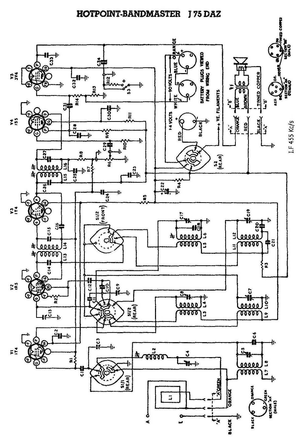 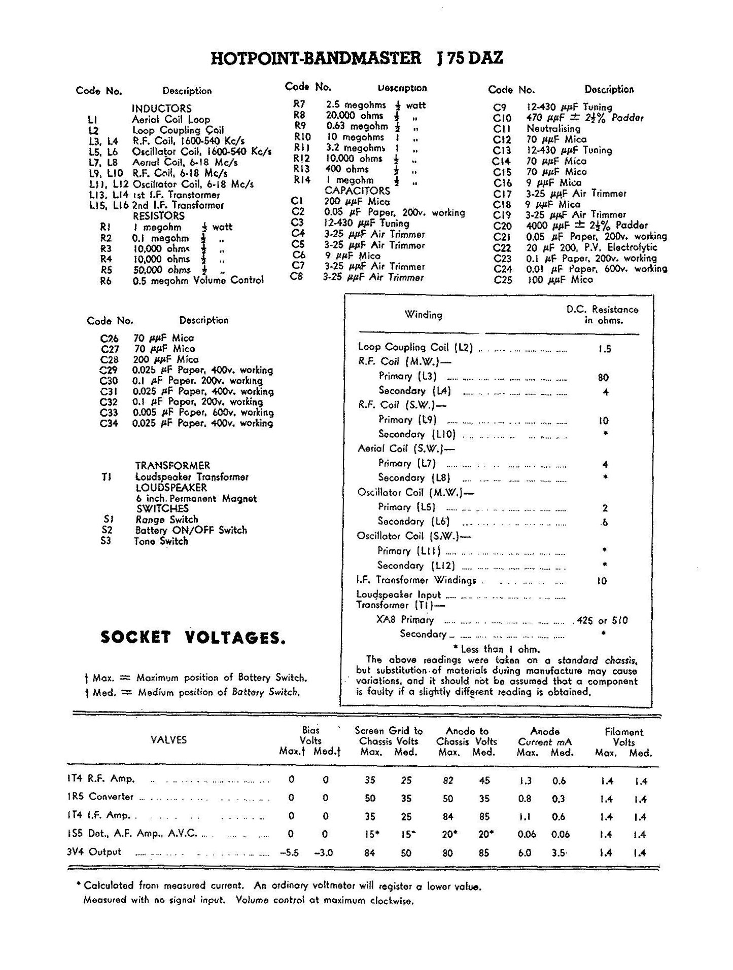 Please click images for higher resolution. |
|
|
« Back ·
1 ·
Next »
|
|
|
You need to be a member to post comments on this forum.
|
|
 mail.vintage-radio.com.au and I will include them in your post.
Sign In
Vintage Radio and Television is proudly brought to you by an era where things were built with pride and made to last.
DISCLAIMER: Valve radios and televisions contain voltages that can deliver lethal shocks. You should not attempt to work on a valve radio or other electrical appliances unless you know exactly what you are doing and have gained some experience with electronics and working around high voltages. The owner, administrators and staff of Vintage Radio & Television will accept no liability for any damage, injury or loss of life that comes as a result of your use or mis-use of information on this website. Please read our Safety Warning before using this website.
WARNING: Under no circumstances should you ever apply power to a vintage radio, television or other electrical appliance you have acquired without first having it checked and serviced by an experienced person. Also, at no time should any appliance be connected to an electricity supply if the power cord is damaged. If in doubt, do not apply power.
Shintara - Keepin' It Real · VileSilencer - Maintain The Rage