
General Discussion
Forum home - Go back to General discussion
|
Emerson model 25A 1932
|
|
|
« Back ·
1 ·
Next »
|
|
|
Return to top of page · Post #: 1 · Written at 9:16:58 PM on 8 April 2019.
|
|

|
Location: Latham, ACT
Member since 21 February 2015 Member #: 1705 Postcount: 2227 |
|
I am fixing this little gem for a good friend and what a education. Valves are 36, 37, 38 and 39. Ac/dc set but not a hot chassis. 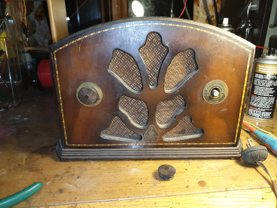 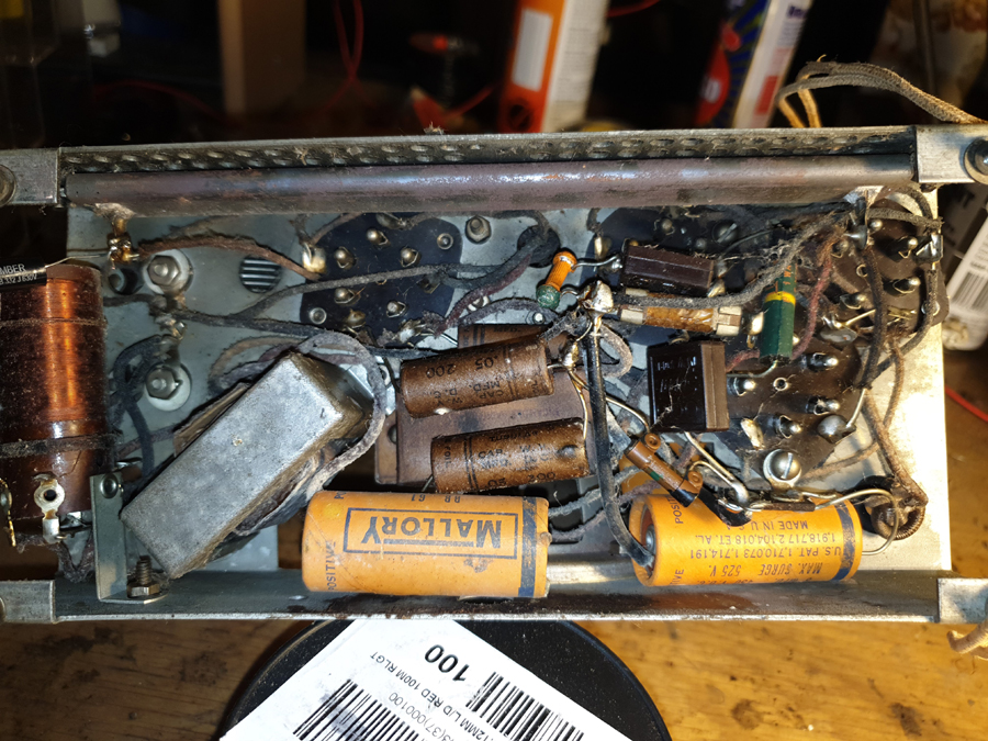 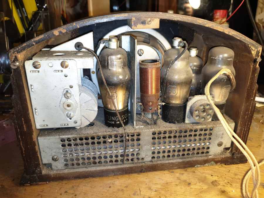 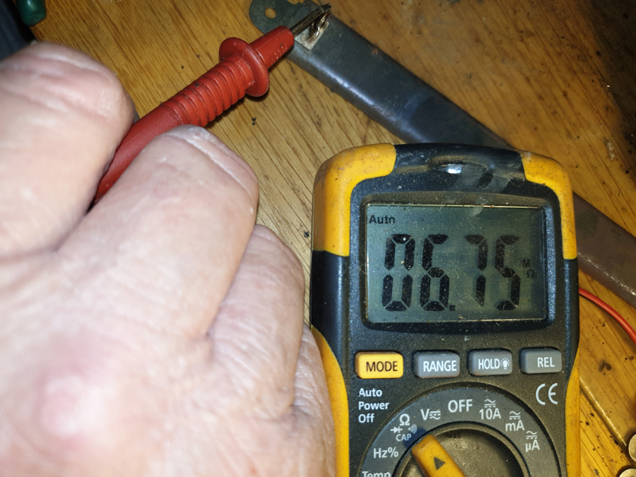 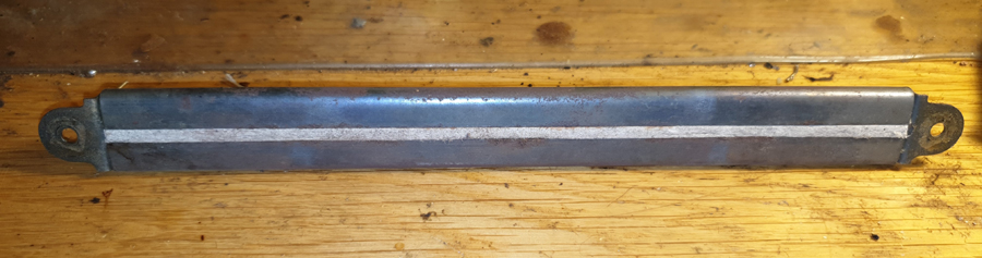 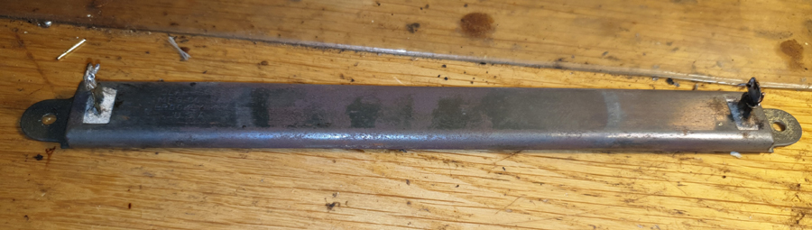 |
|
|
Return to top of page · Post #: 2 · Written at 9:49:35 PM on 8 April 2019.
|
|

|
Location: Wangaratta, VIC
Member since 21 February 2009 Member #: 438 Postcount: 5692 |
|
Interested to see the circuit. 36 is interesting as its a Tetrode. I would suspect that this is an Autodyne (Screen grid). Some of them can be cantankerous. same rules as for a superheterodyne if it is? |
|
|
Return to top of page · Post #: 3 · Written at 10:00:58 PM on 8 April 2019.
|
|
|
|
Location: Latham, ACT
Member since 21 February 2015 Member #: 1705 Postcount: 2227 |
|
Marc I have sent the circuit as well will email it to you. |
|
|
Return to top of page · Post #: 4 · Written at 10:11:25 PM on 8 April 2019.
|
|

|
Location: Sydney, NSW
Member since 28 January 2011 Member #: 823 Postcount: 6940 |
|
Schematic is available on Radiomuseum: |
|
|
Return to top of page · Post #: 5 · Written at 8:50:02 AM on 9 April 2019.
|
|
|
|
Location: Oradell, US
Member since 2 April 2010 Member #: 643 Postcount: 836 |
|
That is a hot chassis design. Though they used a capacitor to the chassis from the line to make it a little less dangerous. |
|
|
Return to top of page · Post #: 6 · Written at 7:28:45 PM on 9 April 2019.
|
|
|
|
Location: Wangaratta, VIC
Member since 21 February 2009 Member #: 438 Postcount: 5692 |
|
NBN was down for a large part of the day just got to the circuit. They are supposed to be upgrading? To what I don't know? The tower should have been put in the nearby citrus orchard. |
|
|
Return to top of page · Post #: 7 · Written at 9:00:08 PM on 9 April 2019.
|
|
|
|
Location: Sydney, NSW
Member since 28 January 2011 Member #: 823 Postcount: 6940 |
|
They are supposed to be upgrading? To what I don't know? |
|
|
Return to top of page · Post #: 8 · Written at 9:07:49 PM on 9 April 2019.
|
|
|
|
Location: Wangaratta, VIC
Member since 21 February 2009 Member #: 438 Postcount: 5692 |
|
I have sent the RCA data for the four valves. The last time I dealt with a triode wired as a rectifier as the #37 is; was a #24 in a Lyric 70 suppling the somewhere around 50-80V to the grid of a #50. |
|
|
Return to top of page · Post #: 9 · Written at 7:16:22 PM on 16 April 2019.
|
|

|
Administrator
Location: Naremburn, NSW
Member since 15 November 2005 Member #: 1 Postcount: 7612 |
|
Photos uploaded. ‾‾‾‾‾‾‾‾‾‾‾‾‾‾‾‾‾‾‾‾‾‾‾‾‾‾‾‾‾‾‾‾‾‾‾‾‾‾‾‾‾‾‾‾‾‾‾‾‾‾‾‾‾‾‾‾‾‾‾‾‾‾‾‾‾‾‾‾ A valve a day keeps the transistor away... |
|
|
« Back ·
1 ·
Next »
|
|
|
You need to be a member to post comments on this forum.
|
|
 300mA draw: 24V would suffice. NB the American mains voltage has increased from 110 to around 120V so the resistor may be too small Dropping from 110V to 6.3 suggests 0.34A; I squared R = 35 Watts to dissipate. With the new voltage we drop near enough to114V. To get 300mA we need 380 ohms. So a chassis mount resistor of 390 Ohms and 40W is probably getting closer.
 Sign In
Vintage Radio and Television is proudly brought to you by an era where things were built with pride and made to last.
DISCLAIMER: Valve radios and televisions contain voltages that can deliver lethal shocks. You should not attempt to work on a valve radio or other electrical appliances unless you know exactly what you are doing and have gained some experience with electronics and working around high voltages. The owner, administrators and staff of Vintage Radio & Television will accept no liability for any damage, injury or loss of life that comes as a result of your use or mis-use of information on this website. Please read our Safety Warning before using this website.
WARNING: Under no circumstances should you ever apply power to a vintage radio, television or other electrical appliance you have acquired without first having it checked and serviced by an experienced person. Also, at no time should any appliance be connected to an electricity supply if the power cord is damaged. If in doubt, do not apply power.
Shintara - Keepin' It Real · VileSilencer - Maintain The Rage