
General Discussion
Forum home - Go back to General discussion
|
Information search for Astor Diamond Dot
|
|
|
Return to top of page · Post #: 1 · Written at 8:15:11 PM on 20 May 2018.
|
|
|
|
Location: Molesworth, TAS
Member since 19 May 2018 Member #: 2250 Postcount: 13 |
|
Hello all, |
|
|
Return to top of page · Post #: 2 · Written at 10:19:45 PM on 20 May 2018.
|
|

|
Location: Melbourne, VIC
Member since 20 September 2011 Member #: 1009 Postcount: 1257 |
|
Hello Matthew & welcome to the Forums. |
|
|
Return to top of page · Post #: 3 · Written at 6:06:54 PM on 21 May 2018.
|
|
|
|
Location: Molesworth, TAS
Member since 19 May 2018 Member #: 2250 Postcount: 13 |
|
Thank you for the reply. 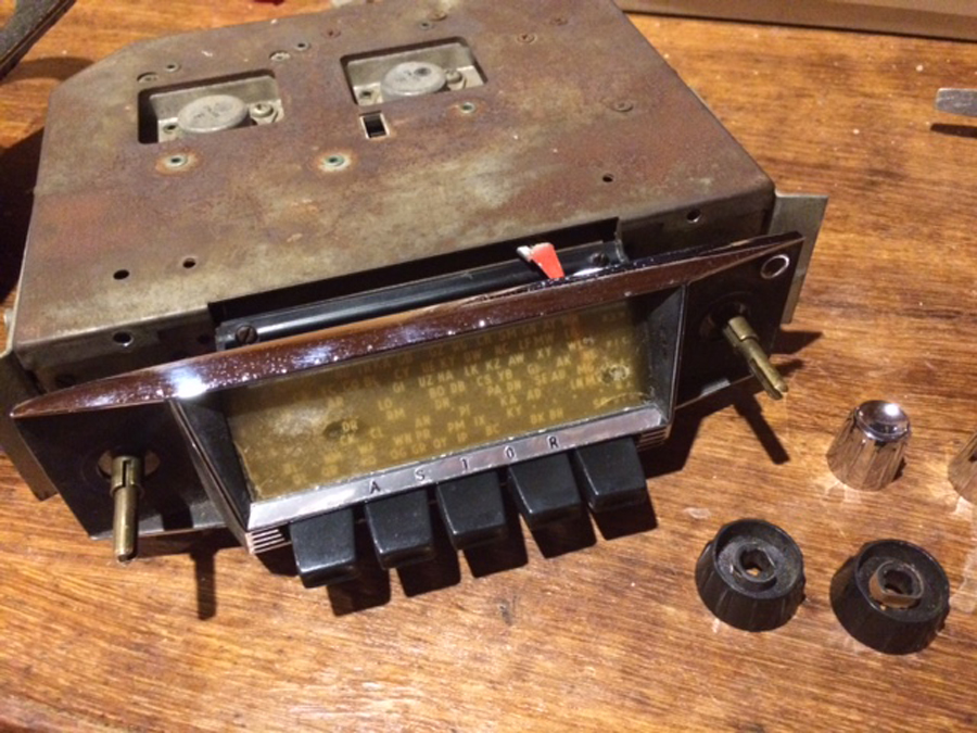 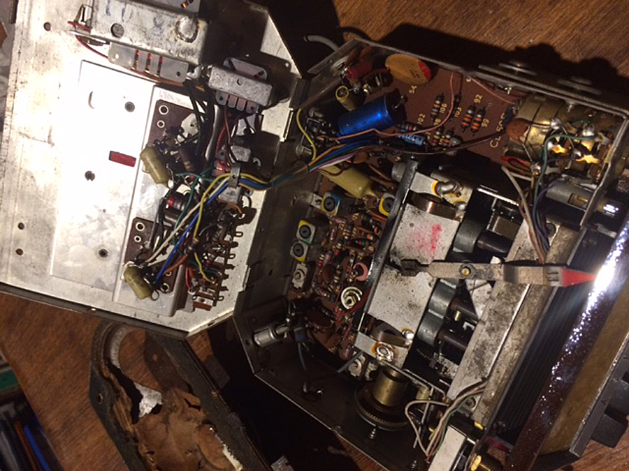 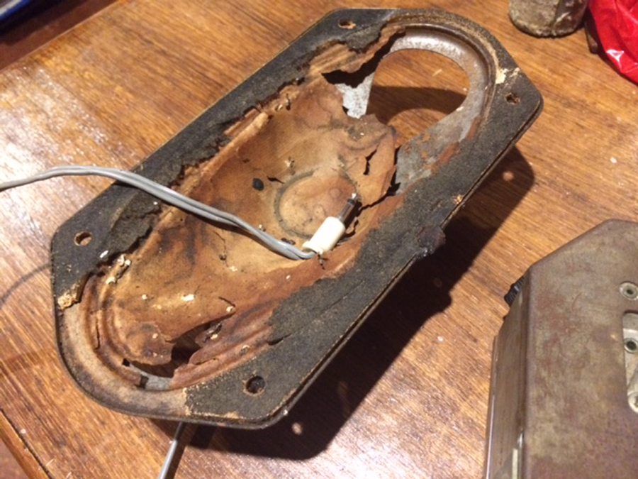 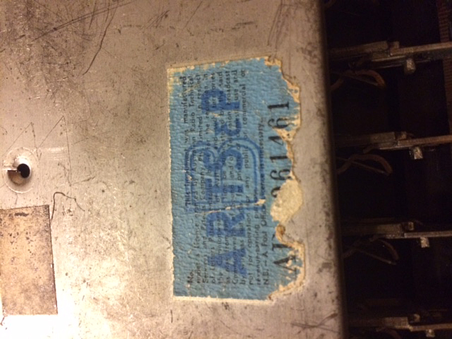 |
|
|
Return to top of page · Post #: 4 · Written at 9:06:26 PM on 21 May 2018.
|
|
|
|
Location: Melbourne, VIC
Member since 20 September 2011 Member #: 1009 Postcount: 1257 |
|
Does this radio have 11 transistors including 2 TO3 type AT1138 power transistors on the outside of the case? |
|
|
Return to top of page · Post #: 5 · Written at 10:02:44 PM on 21 May 2018.
|
|
|
|
Location: Belrose, NSW
Member since 31 December 2015 Member #: 1844 Postcount: 2652 |
|
I doubt Coralpolyp would have any reason to know what a TO3 transistor case looked like... |
|
|
Return to top of page · Post #: 6 · Written at 10:50:44 PM on 21 May 2018.
|
|
|
|
Location: Molesworth, TAS
Member since 19 May 2018 Member #: 2250 Postcount: 13 |
|
Thanks for the link... |
|
|
Return to top of page · Post #: 7 · Written at 11:07:12 PM on 21 May 2018.
|
|
|
|
Location: Molesworth, TAS
Member since 19 May 2018 Member #: 2250 Postcount: 13 |
|
Using the power of the interweb, I think I have identified eight transistors, but I can’t find a ninth one. |
|
|
Return to top of page · Post #: 8 · Written at 11:59:16 PM on 21 May 2018.
|
|

|
Administrator
Location: Naremburn, NSW
Member since 15 November 2005 Member #: 1 Postcount: 7574 |
|
Photos uploaded. ‾‾‾‾‾‾‾‾‾‾‾‾‾‾‾‾‾‾‾‾‾‾‾‾‾‾‾‾‾‾‾‾‾‾‾‾‾‾‾‾‾‾‾‾‾‾‾‾‾‾‾‾‾‾‾‾‾‾‾‾‾‾‾‾‾‾‾‾ A valve a day keeps the transistor away... |
|
|
Return to top of page · Post #: 9 · Written at 9:11:46 AM on 22 May 2018.
|
|
|
|
Location: Melbourne, VIC
Member since 20 September 2011 Member #: 1009 Postcount: 1257 |
|
I'm now guessing it could be a Astor Diamond Dot PDC12J if it has a dual-polarity switch. There is a similar version, Air Chief PNC12N, negative earth, which is designed to suit HD & HR Holdens. Then there are what appears to be later negative earth versions using some different transistor types, models PNC12P & PNC12Q. All models mentioned appear to be basically your standard Astor 11 transistor push-button car radio. |
|
|
Return to top of page · Post #: 10 · Written at 12:42:58 PM on 22 May 2018.
|
|

|
Location: Penrith, NSW
Member since 7 April 2012 Member #: 1128 Postcount: 403 |
|
Have a look for the missing transistor inbetween the two output transistors on the swing up cover. ‾‾‾‾‾‾‾‾‾‾‾‾‾‾‾‾‾‾‾‾‾‾‾‾‾‾‾‾‾‾‾‾‾‾‾‾‾‾‾‾‾‾‾‾‾‾‾‾‾‾‾‾‾‾‾‾‾‾‾‾‾‾‾‾‾‾‾‾ I love the smell of ozone in the morning. |
|
|
Return to top of page · Post #: 11 · Written at 6:30:05 PM on 22 May 2018.
|
|
|
|
Location: Molesworth, TAS
Member since 19 May 2018 Member #: 2250 Postcount: 13 |
|
It does have a dual polarity switch. |
|
|
Return to top of page · Post #: 12 · Written at 6:56:02 PM on 22 May 2018.
|
|
|
|
Location: Molesworth, TAS
Member since 19 May 2018 Member #: 2250 Postcount: 13 |
|
It does look like you’re right, it appears to be a PD-C12J. Thank you! |
|
|
Return to top of page · Post #: 13 · Written at 9:30:29 AM on 23 May 2018.
|
|

|
Location: Wangaratta, VIC
Member since 21 February 2009 Member #: 438 Postcount: 5634 |
|
We need the dimensions of the speaker; A lot were 5 x 7 inches. |
|
|
Return to top of page · Post #: 14 · Written at 11:28:36 AM on 23 May 2018.
|
|
|
|
Location: Molesworth, TAS
Member since 19 May 2018 Member #: 2250 Postcount: 13 |
|
Hello Marc |
|
|
Return to top of page · Post #: 15 · Written at 12:07:19 PM on 23 May 2018.
|
|
|
|
Location: Melbourne, VIC
Member since 20 September 2011 Member #: 1009 Postcount: 1257 |
|
I would definitely replace the disc capacitors. They are called Ducon Red Caps, distinguished by the red mark on top. These red caps often turn into resistors. You can measure the leakage of these Red Caps with the high ohms range on a multi-meter. In the past I've replaced them with Greencaps, ceramic or monolithic caps with the same value, though I am not an expert on which would be the best type to use. The blue Philips electrolytics I've found to be reliable as with the mustard Philips poly caps. Get rid of any cap, except perhaps the Styroseals, with Ducon written on it. |
|
|
You need to be a member to post comments on this forum.
|
|
Sign In
Vintage Radio and Television is proudly brought to you by an era where things were built with pride and made to last.
DISCLAIMER: Valve radios and televisions contain voltages that can deliver lethal shocks. You should not attempt to work on a valve radio or other electrical appliances unless you know exactly what you are doing and have gained some experience with electronics and working around high voltages. The owner, administrators and staff of Vintage Radio & Television will accept no liability for any damage, injury or loss of life that comes as a result of your use or mis-use of information on this website. Please read our Safety Warning before using this website.
WARNING: Under no circumstances should you ever apply power to a vintage radio, television or other electrical appliance you have acquired without first having it checked and serviced by an experienced person. Also, at no time should any appliance be connected to an electricity supply if the power cord is damaged. If in doubt, do not apply power.
Shintara - Keepin' It Real · VileSilencer - Maintain The Rage