Welcome to Australia's only Vintage Radio and Television discussion forums. You are not logged in. Please log in below, apply for an account or retrieve your password.
Australian Vintage Radio Forums
  Home  ·  About Us  ·  Discussion Forums  ·  Glossary  ·  Outside Links  ·  Policies  ·  Services Directory  ·  Safety Warnings  ·  Tutorials

General Discussion

Forum home - Go back to General discussion

 AWA line compensation unit. What is it for?
« Back · 1 · 2 · Next »
 Return to top of page · Post #: 1 · Written at 1:46:55 PM on 13 May 2018.
Muzzery's Gravatar
 Location: Maleny, QLD
 Member since 28 February 2018
 Member #: 2218
 Postcount: 95

Hi, all. I wonder if anyone knows why this may have been used for? It is excess to my requirements, and I might be able to move it on gumtree etc, if only I knew it’s intended use. Or perhaps it is better sent to the scrap metal man? It transforms 240 volt to 115, about 2900 watt I think. It would suit American tools etc in Australia, although its outlet (I think) is an Aussie type plug.
I guess it came from the telecommunications industry.
Thanks, Murray.

AWA Line Compensation Unit


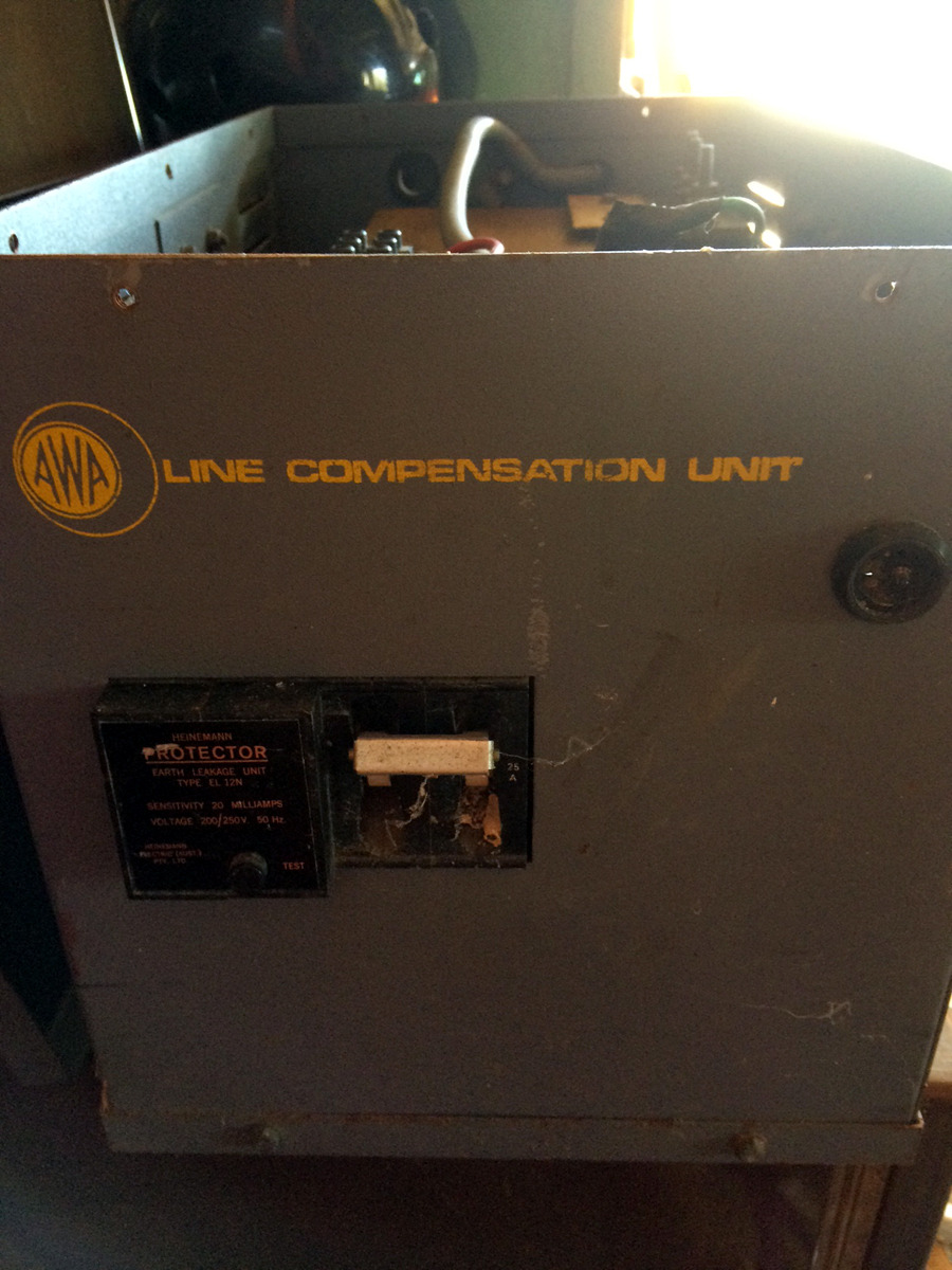
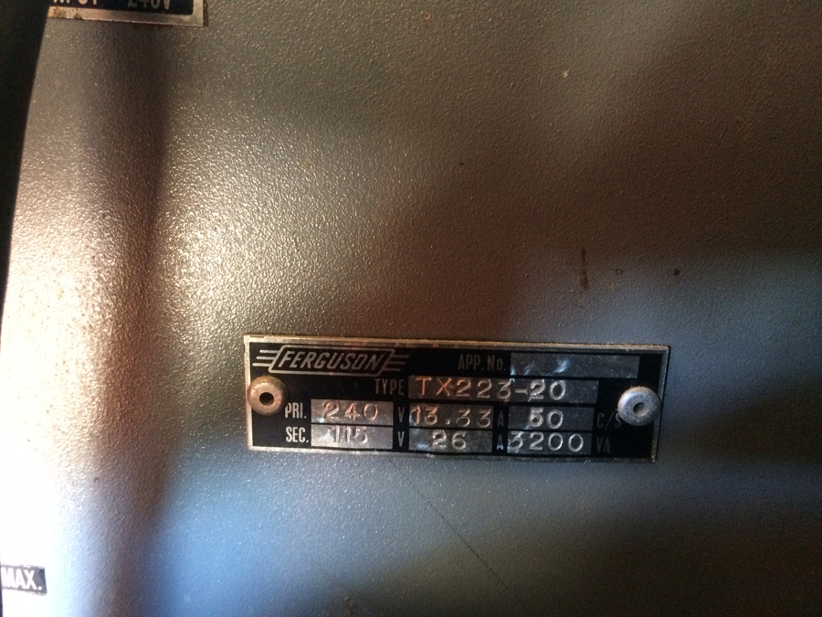
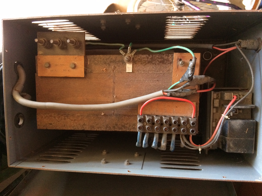
 Return to top of page · Post #: 2 · Written at 3:55:43 PM on 13 May 2018.
Marcc's avatar
 Location: Wangaratta, VIC
 Member since 21 February 2009
 Member #: 438
 Postcount: 5254

There is quite a bit of 110-115V equipment about. Make sure its a transformer & not an "auto-transformer. I have one of both. One can be used for isolation, auto transformer: No.

Marketable, don't know Tag & Test rules for second hand goods apply in Qld (If they have them?).


 Return to top of page · Post #: 3 · Written at 5:54:36 PM on 13 May 2018.
GTC's avatar
 GTC
 Location: Sydney, NSW
 Member since 28 January 2011
 Member #: 823
 Postcount: 6687

It would suit American tools etc in Australia

Not if they require 60Hz mains frequency (ours is 50Hz).


 Return to top of page · Post #: 4 · Written at 8:15:32 PM on 13 May 2018.
Muzzery's Gravatar
 Location: Maleny, QLD
 Member since 28 February 2018
 Member #: 2218
 Postcount: 95

Good point, I didn’t consider it being 50Hz. I will need to look harder, but it seems to have varying voltage “taps” coming off the winding, this might suggest auto transformer? Is this similar to a variac in principle?


 Return to top of page · Post #: 5 · Written at 8:26:21 PM on 13 May 2018.
Brad's avatar
 Administrator
 Location: Naremburn, NSW
 Member since 15 November 2005
 Member #: 1
 Postcount: 7301

Isolation transformers can have tappings too. The only way to find out is to put an ohm meter across one of the primary terminals and one of the secondary terminals. If there is continuity then it is not an isolation transformer.


‾‾‾‾‾‾‾‾‾‾‾‾‾‾‾‾‾‾‾‾‾‾‾‾‾‾‾‾‾‾‾‾‾‾‾‾‾‾‾‾‾‾‾‾‾‾‾‾‾‾‾‾‾‾‾‾‾‾‾‾‾‾‾‾‾‾‾‾
A valve a day keeps the transistor away...

 
 Return to top of page · Post #: 6 · Written at 9:19:17 PM on 13 May 2018.
GTC's avatar
 GTC
 Location: Sydney, NSW
 Member since 28 January 2011
 Member #: 823
 Postcount: 6687

A good in-focus photo or two may help.


 Return to top of page · Post #: 7 · Written at 10:05:36 PM on 13 May 2018.
Marcc's avatar
 Location: Wangaratta, VIC
 Member since 21 February 2009
 Member #: 438
 Postcount: 5254

The ring tone in the old phones was 110VAC. So it is possible that it is like the transformer in the VCT Valve & Circuit tester, which has a switched set of tappings , that, with the aid of the meter, sets the operating voltage so that all tests are at the same voltage.

It may be a bit on the bulky side, which would indicate that its "continuous rated". Viz designed to run 24/7.

Marc


 Return to top of page · Post #: 8 · Written at 2:23:33 PM on 14 May 2018.
Kakadumh's Gravatar
 Location: Darlington, WA
 Member since 30 March 2016
 Member #: 1897
 Postcount: 183

Would never have been anything to do with phone ringing current as that was almost always generated by specially made generator units that provided 75V AC . 16.666Hz. That was used to ring the magneto bells in the phones.

The same generator produced the various tones which then were interrupted at whatever periodicity was required by cam driven contact assemblies.

Most exchanges used a DC (48V) motor to drive the generator as an all in one unit with the tone interrupting cams across one end at right angles to the main shaft.

Bigger exchanges used and AC motor to drive the much bigger ringing & tone generator. Small country sites could have a small ringing machine or in many cases a unit driven by the mains 240V would stepdown the 240V to 75V and give it what they called a "sub cycle" treatment that chopped the 50Hz into 16.666 Hz as many of the older magneto bells would not reliably respond to 50Hz ringing signal & the tones were generated by crude ocscillators and the tones thus produced interrupted in the cadence required by some neat relay trickery.

When things went digital all the above ceased and each 128 line unit had its own ringing & tone generator all solid state & driven by the system clock signal.

What the transformer possibly is is a 240-115V adjustable step down transformer often fitted with a volt meter on the OP & used to power many of the older 16mm projectors that used 115V x1000Watt lamps. The VM if fitted was red lined at 115V and one adjusted that to get as close to 115V as possible. Most were rated at 1500Watts and are extremely heavy and in some cases weighed more than the 16mm projector.
Australian PO used lots of instructional 16mm films in all their training schools up to the late 1980's. Bell & Howell were the common use 16mm machines with the odd Siemens or Ampro projector used...Siemens had no transformer but still used 115V lamps with 220/240V motor & amp circuits. The lamp was fed with 240V via an adjustable resistance unit built in around the lamphouse and ran super HOT when in use.

Lindsay.


 Return to top of page · Post #: 9 · Written at 6:21:00 PM on 14 May 2018.
Ian Robertson's Gravatar
 Location: Belrose, NSW
 Member since 31 December 2015
 Member #: 1844
 Postcount: 2371

It's nothing to do with AC mains power.

A Line Compensation Unit was used in the radio broadcast industry when sending radio programs via PMG landlines It was used to compensate for line losses and correct the frequency response. Also to match impedances so the long line didn't echo.

Now it's just possible that what you have is a box that's been re-purposed to hold a 240 to 110v transformer. But what I said was its original purpose.

WHOA, now I see pics! I'm wrong! It's obviously a POWER compensation device!


 Return to top of page · Post #: 10 · Written at 8:00:22 PM on 14 May 2018.
BringBackTheValve's Gravatar
 Location: Linton, VIC
 Member since 30 December 2016
 Member #: 2028
 Postcount: 467

As an "Installer" with Telecom Australia I visited many exchanges and remember the Ring Tone gennys very well.
They looked like someone stuck a bench grinder on a pedestal and replaced the grinding wheel with a cam driving several followers operating switch contacts protected in what I thought was a clear perspex box.

For some reason I found them rather hypnotic, and could watch them operating for lengthy periods.
Silent and dependable, pure mechanical precision. The old term "---like a Swiss watch " comes to mind. Some of the larger exchanges had a standby unit close by. (When I say silent, I mean I could not hear them over the crashing of crossbar switching)

In one exchange (Northcote VIC) a friendly "maito" took time to show me how they worked. I was astonished that all out-going calls depended on this single equipment for ring, dial, and busy tone. Wonderful technology at it' very peak.

The same "maito" asked me to bring in an old gyro from an antique artificial horizon I owned. I could never drive it no matter what type of current I fed it. He brought in a devilish rotary device---a motor driven genny, first time I have ever seen one---three phase, hooked it up to my gyro and got the motor genny up to speed (400Hz) as the gyro began spinning----FANTASTIC!


Thanks Kakadumh for the memories.


 Return to top of page · Post #: 11 · Written at 10:12:12 PM on 14 May 2018.
GTC's avatar
 GTC
 Location: Sydney, NSW
 Member since 28 January 2011
 Member #: 823
 Postcount: 6687

For some reason I found them rather hypnotic, and could watch them operating for lengthy periods.

Enjoy: https://www.youtube.com/watch?v=lhxTV1eqqsg


 Return to top of page · Post #: 12 · Written at 10:31:18 PM on 14 May 2018.
BringBackTheValve's Gravatar
 Location: Linton, VIC
 Member since 30 December 2016
 Member #: 2028
 Postcount: 467

Nice one, many thanks GTC.


 Return to top of page · Post #: 13 · Written at 6:54:34 PM on 15 May 2018.
Kakadumh's Gravatar
 Location: Darlington, WA
 Member since 30 March 2016
 Member #: 1897
 Postcount: 183

Interesting to see those ringing machines going on the couple of YouTube clips.

Not exactly on topic but the ringing machines were quite a work of art as the DC motor armature was interwound with a 75V 17Hz AC winding which came out through the slip rings.
To even the load on the ringer there were 3 sets of cams breaking the ringing current up into 3 distinct feeds of 0.2 sec on, 0.4sec off, 02 sec on & then 2 seconds of off.

Each of the ring feeds was offset from the previous feed of the 1 second ringing signal so that as one feed ended supplying ring voltage to the exchange the other feeds would follow on so to a large degree the load on the motor was reasonably even.

It was a shunt wound DC motor so reasonably stable in terms of speed and they all had a small adjustable resistor which could alter the field current of the motor so one could set the speed quite accurately which became VERY important as fax machines made their way into the phone network.
This was because the big drum like end on the machines shown (opposite end to the gear box and cams with contact assemblies) as inside that drum was a very complex number of toothed rotor tone generators to generate Dial Tone, Busy Tone & Ringing Tone.

If any exchange machine was running off speed then the fax machines had trouble detecting dial tone sometimes but busy tone had to be exactly on 400Hz else the fax could not discern a busy connection and would screw up the fax attempt.

Busy tone & Number Unobtainable Tone were the same frequency and the one tone drum inside that big bulbous end supplied the 400Hz base tone which the cam driven contacts then broke up to the correct tone cadence.

Dial tone was basically 33Hz with some harmonics inbuilt into the design, Ring Tone was originally 135Hz & modulated by the 17Hz ringing current. Later machines had the ringing tone changed to 400Hz & still modulated by the 17Hz ringing current to keep in line with International Standards.
So over the years there was a lot of monkeying around with ringing machines and the blessed fax machines created the worst of it because when makers of fax machines approached whomever within the telephone industry for the specifications of the tones apparently the frequencies were quoted and more or less taken as being EXACT..like 400Hz spot on.

That with solid state stuff was easy to do and they made their fax machines to look for Busy Tone at EXACTLY 400Hz...A far different story for telephone exchanges with varying DC voltages and actual AC load variations on the machines meant that the 400Hz signal was NOT exactly 400Hz every time.

So fax machines played up & getting the huge number of ringing machines in use across Australia correctly on speed was an enormous task with the fax machine makers & users breathing down our necks.

It was NOT helped by the Standby machines which when called upon to take the load almost always ran slow until they warmed up. So then it was decreed that exchange staff should swap machines once a week which raised another issue that the Engineers overlooked in that many of the early ringing machine racks supplied did NOT allow for a routine swap over as one machine was the Main unit and the other was Standby ONLY and a failure of the Standby unit meant that the exchange shutdown. The design allows for the Main to be always running and when it failed it was meant to be fixed ASAP and the machines swapped back.

Thus further mods came along to allow either machine to be Main and the other would always take over if the running unit faltered.

It was with much relief that staff welcomed the AXE digital system where each 128 Line group had its own solid state ring & tone generated just to feed that 128 line group.

As the older Ericsson crossbar gear was decommissioned the older ringing machines all went as well.

NOW ALL the Telstra digital switching for local exchanges is going as the NBN takes hold and ALL your calls will be switched by the various ISP's via their SIP networks and already we are seeing issues with Tone Standards from the various ISP's switching gear.

I volunteer at a local FM radio station and we do the odd OB (outside broadcast) & we use a Tieline device to call via the switched phone network to the studio which has a Tieline device attached to the phone line.

With the wonders of digital signal processing we can squeeze a 8kHz Mono signal from the OB point down a phone line that has a bandwidth of just over 3kHz.

The Tieline units have to recognise the Dial Tone & the Busy Tone & guess what at times they are NOT able to do so & the OB is in strife.
So standards have slipped already.

The solution is to establish the OB via the Internet using allocated IP Addresses via the data network associated with the 3G & 4G networks. Then we can squeeze a 15kHz Stereo signal via that system.

Lindsay


 Return to top of page · Post #: 14 · Written at 7:26:12 PM on 15 May 2018.
GTC's avatar
 GTC
 Location: Sydney, NSW
 Member since 28 January 2011
 Member #: 823
 Postcount: 6687

Thanks. That's the best description of the operation of mechanical ring generators that I've ever read.


 Return to top of page · Post #: 15 · Written at 7:45:26 PM on 15 May 2018.
Arcadus's avatar
 Location: Nildottie, SA
 Member since 7 April 2018
 Member #: 2236
 Postcount: 43

Thanks for the references to the step X step exchanges. I started with Telecom (1970s) in Unley exchange containing pre2000 (strowger),2000 and Xbar.
The sound brings back memories. I have a pre2000 group selector and final selector in the shed from when the pre2000 was decommissioned late 70s.


« Back · 1 · 2 · Next »
 You need to be a member to post comments on this forum.

Sign In

Username:
Password:
 Keep me logged in.
Do not tick box on a computer with public access.