
General Discussion
Forum home - Go back to General discussion
|
STC Model 205 (Jelly Mould)
|
|
|
« Back ·
1 ·
Next »
|
|
|
Return to top of page · Post #: 1 · Written at 7:13:24 PM on 12 July 2017.
|
|
|
|
Location: Sydney, NSW
Member since 22 May 2017 Member #: 2114 Postcount: 120 |
|
Hi Guys |
|
|
Return to top of page · Post #: 2 · Written at 8:24:42 PM on 12 July 2017.
|
|

|
Location: Latham, ACT
Member since 21 February 2015 Member #: 1705 Postcount: 2220 |
|
Mine has a plastic cover. what are you calling the dial face , is it the cover? Actually my Broadcast model also has a plastic cover. |
|
|
Return to top of page · Post #: 3 · Written at 8:33:28 AM on 13 July 2017.
|
|
|
|
Location: Sydney, NSW
Member since 22 May 2017 Member #: 2114 Postcount: 120 |
|
I am referring to the clear curved cover over the dial. I also am now aware that there are two models the 205 and B105, the 205 had the Broadcast/MW and four knobs. I assume the Curved Clear Dial cover on both is made of the same material. I belive both these were made around 1946-48. Any other info on this radio that anyone has will be appreciated and if anyone wants to sell theirs send me am email. |
|
|
Return to top of page · Post #: 4 · Written at 9:49:10 AM on 13 July 2017.
|
|
|
|
Location: Belrose, NSW
Member since 31 December 2015 Member #: 1844 Postcount: 2677 |
|
Cut To Size Plastics can cut you one from 0.5mm clear lexan which will flex to fit the curve. |
|
|
Return to top of page · Post #: 5 · Written at 7:18:13 AM on 14 July 2017.
|
|

|
Location: Wangaratta, VIC
Member since 21 February 2009 Member #: 438 Postcount: 5663 |
|
Many of those where it was curved were Nitro-cellulose plastic, which was identifiable by its tendency to go brown; That being caused by that particular plastic starting to decompose from day one. Not that plastics of the fifties used in coil formers & such things are not doing the same, differently & I have seen a few decomposing. Wood, Ceramic & Bakelite are the survivors, in early stuff. |
|
|
Return to top of page · Post #: 6 · Written at 3:29:49 PM on 19 July 2017.
|
|
|
|
Location: Sydney, NSW
Member since 22 May 2017 Member #: 2114 Postcount: 120 |
|
So I have now another radio to restore, though I was looking at the 205, I ended up with the STC D105, I really like the look of the "Jelly Mould" as it is called, but it looks like a modification has been made, though I have not taken it out of the cabinet as yet, on the back is a threw way toggle switch where the the knob should be. Can anyone conform what the knob on the rear on the orginal would have been for, was it the on/off switch? I assume the knobs on each side is volume and the other is definitely for tuning. |
|
|
Return to top of page · Post #: 7 · Written at 4:18:00 PM on 19 July 2017.
|
|

|
Location: Sydney, NSW
Member since 28 January 2011 Member #: 823 Postcount: 6911 |
|
There's a photo of the rear of the B105 chassis here: |
|
|
Return to top of page · Post #: 8 · Written at 7:10:10 PM on 19 July 2017.
|
|
|
|
Location: Sydney, NSW
Member since 22 May 2017 Member #: 2114 Postcount: 120 |
|
Thanks GTC, I did go Initially to Radiomuseum but only looked at the D105 which is what this radio is labelled as on the underside, with the 6V6G crossed out and replaced with a 6F6G valve I assume done at the factory, I am not sure exactly what the other difference is to the B105 and the photo on Radiomuseum of the D105 is only a front view. I could not see an on/off switch on the D105 schematic either, so it must be a previous owner mod. |
|
|
Return to top of page · Post #: 9 · Written at 9:22:54 PM on 19 July 2017.
|
|

|
Location: Hill Top, NSW
Member since 18 September 2015 Member #: 1801 Postcount: 2233 |
|
Someone probably didn't have a spare 6V6G and threw in the 6F6G in instead, as they have the same connections. |
|
|
Return to top of page · Post #: 10 · Written at 9:58:22 PM on 19 July 2017.
|
|
|
|
Location: Latham, ACT
Member since 21 February 2015 Member #: 1705 Postcount: 2220 |
|
Neither of the jellymoulds had on / off switches. |
|
|
Return to top of page · Post #: 11 · Written at 12:16:21 AM on 20 July 2017.
|
|
|
|
Location: Wangaratta, VIC
Member since 21 February 2009 Member #: 438 Postcount: 5663 |
|
The bias and the speaker transformer, (the latter being more difficult to identify) may be the clues as to what went on there. The 6V6 will have around - 4V less |
|
|
Return to top of page · Post #: 12 · Written at 8:17:21 AM on 20 July 2017.
|
|
|
|
Location: Sydney, NSW
Member since 22 May 2017 Member #: 2114 Postcount: 120 |
|
Hi Marc, |
|
|
Return to top of page · Post #: 13 · Written at 10:07:46 AM on 20 July 2017.
|
|
|
|
Location: Wangaratta, VIC
Member since 21 February 2009 Member #: 438 Postcount: 5663 |
|
There are often factory mods and around war time they were common. One HMV changed to a Philips valve as WD scarpered off with all of the 6B8"s. If You look carefully, there was at that period, a reversion to 6pin valves after actually starting to change to octal. |
|
|
Return to top of page · Post #: 14 · Written at 2:27:02 PM on 12 August 2017.
|
|

|
Location: Beechmont, QLD
Member since 10 April 2009 Member #: 465 Postcount: 109 |
|
I have a B105 and a D105 here. The former has a glass transparency, the other is plastic, presumably celluloid. |
|
|
« Back ·
1 ·
Next »
|
|
|
You need to be a member to post comments on this forum.
|
|
 250V than 6F6 on grid one.
  Luckily I had a spare. What I did not have was a 6AG6G that would fit. I did have a couple, but the 6AG6G came in two sizes, and only the smaller size will fit, and I only had the larger size. I ended up retaining the 6V6GT but altering the bias so that it drew the same current as the original 6AG6G. I have come across this three or four times: a high slope valve being replaced by a lower slope valve resulting in excessive current and overheated transformers.
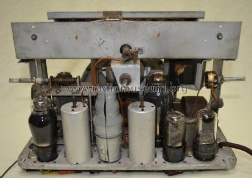
Sign In
Vintage Radio and Television is proudly brought to you by an era where things were built with pride and made to last.
DISCLAIMER: Valve radios and televisions contain voltages that can deliver lethal shocks. You should not attempt to work on a valve radio or other electrical appliances unless you know exactly what you are doing and have gained some experience with electronics and working around high voltages. The owner, administrators and staff of Vintage Radio & Television will accept no liability for any damage, injury or loss of life that comes as a result of your use or mis-use of information on this website. Please read our Safety Warning before using this website.
WARNING: Under no circumstances should you ever apply power to a vintage radio, television or other electrical appliance you have acquired without first having it checked and serviced by an experienced person. Also, at no time should any appliance be connected to an electricity supply if the power cord is damaged. If in doubt, do not apply power.
Shintara - Keepin' It Real · VileSilencer - Maintain The Rage