
General Discussion
Forum home - Go back to General discussion
|
AWA Wooden Mantle Radiola
|
|
|
Return to top of page · Post #: 16 · Written at 7:26:02 PM on 12 August 2017.
|
|
|
|
Location: Milton, NSW
Member since 27 June 2016 Member #: 1945 Postcount: 55 |
|
That would certainly align with Sirwin's observation that R91was stamped on the chassis. My guess was purely based on the ARTS&P sticker prefix and the valve lineup. |
|
|
Return to top of page · Post #: 17 · Written at 2:52:19 PM on 13 October 2017.
|
|

|
Location: Latham, ACT
Member since 21 February 2015 Member #: 1705 Postcount: 2155 |
|
Well I have had a start on this one. its been gotten at . I discovered that the original 16μF cap cans were left in circuit and the guy had used the terminals as a tag strip for 8μF electros ( they replaced the 16μF with a 8μF ) I am told that this shouldn't matter but using the tags from the originals is a no no. discovering this I remedied the situation. The dial lights however lit up which means part of the transformer is good. 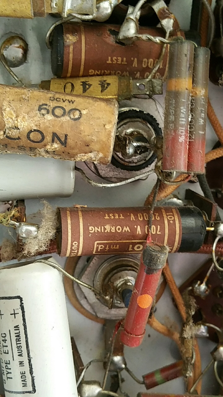  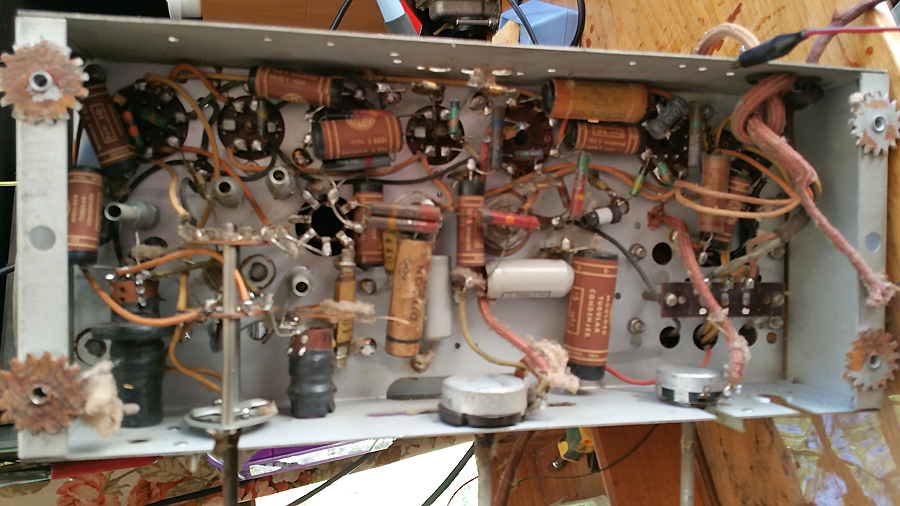 |
|
|
Return to top of page · Post #: 18 · Written at 6:23:56 PM on 13 October 2017.
|
|

|
Location: Hill Top, NSW
Member since 18 September 2015 Member #: 1801 Postcount: 2015 |
|
*deleted |
|
|
Return to top of page · Post #: 19 · Written at 8:37:25 PM on 13 October 2017.
|
|
|
|
Location: Latham, ACT
Member since 21 February 2015 Member #: 1705 Postcount: 2155 |
|
The wires are not touching any of the chassis , so the fault is internal I would think. |
|
|
Return to top of page · Post #: 20 · Written at 8:39:28 PM on 13 October 2017.
|
|

|
Location: Sydney, NSW
Member since 28 January 2011 Member #: 823 Postcount: 6687 |
|
An insulation test should result in a breakdown condition, by the sound of it. |
|
|
Return to top of page · Post #: 21 · Written at 10:49:29 PM on 13 October 2017.
|
|

|
Administrator
Location: Naremburn, NSW
Member since 15 November 2005 Member #: 1 Postcount: 7302 |
|
Photos uploaded to Post 17. ‾‾‾‾‾‾‾‾‾‾‾‾‾‾‾‾‾‾‾‾‾‾‾‾‾‾‾‾‾‾‾‾‾‾‾‾‾‾‾‾‾‾‾‾‾‾‾‾‾‾‾‾‾‾‾‾‾‾‾‾‾‾‾‾‾‾‾‾ A valve a day keeps the transistor away... |
|
|
Return to top of page · Post #: 22 · Written at 12:03:31 AM on 14 October 2017.
|
|
|
|
Location: Hill Top, NSW
Member since 18 September 2015 Member #: 1801 Postcount: 2015 |
|
That radio looks much like a console I repaired then donated to a friend... especially if the speaker has a special plug that is mounted on the speaker itself. |
|
|
Return to top of page · Post #: 23 · Written at 12:48:51 AM on 14 October 2017.
|
|

|
Location: Wangaratta, VIC
Member since 21 February 2009 Member #: 438 Postcount: 5254 |
|
I am not sure as to how you tested this: I would on looking at it not dare power it on seeing the mistakes. One of the first things not done is to power a set like that. Even then, when powering, all of the valves & globes should be removed for transformer testing. To avoid problems with HV DC when testing otherwise, 5Y3 should be on the bench until all that side is repaired. |
|
|
Return to top of page · Post #: 24 · Written at 7:50:17 AM on 14 October 2017.
|
|
|
|
Location: Latham, ACT
Member since 21 February 2015 Member #: 1705 Postcount: 2155 |
|
I powered it on after I had corrected the obvious issues. I never power on with the old caps in place. |
|
|
Return to top of page · Post #: 25 · Written at 6:28:31 PM on 14 October 2017.
|
|
|
|
Location: Latham, ACT
Member since 21 February 2015 Member #: 1705 Postcount: 2155 |
|
Well I am getting another transformer for this one shortly so hopefully there will be some music. |
|
|
Return to top of page · Post #: 26 · Written at 10:39:35 PM on 14 October 2017.
|
|
|
|
Location: Wangaratta, VIC
Member since 21 February 2009 Member #: 438 Postcount: 5254 |
|
You can do some testing by pulling the rectifier tube, thereby Killing the HV DC & all of its woes. |
|
|
Return to top of page · Post #: 27 · Written at 7:29:04 PM on 15 October 2017.
|
|
|
|
Location: Latham, ACT
Member since 21 February 2015 Member #: 1705 Postcount: 2155 |
|
Ok the transformer that I have obtained is out of a seven band table set. It also has settings for 110 volt ( pacific islands ). I wont be using any other voltages and have never done this before so how would I wire it up. I will get a tech to check this its just that I am trying to work out where I terminate the active and the neutral. |
|
|
Return to top of page · Post #: 28 · Written at 8:56:34 PM on 15 October 2017.
|
|
|
|
Location: Sydney, NSW
Member since 28 January 2011 Member #: 823 Postcount: 6687 |
|
Use your Variac to work out the windings and voltages. Set the Variac to (say) 10 volts and connect it to various pairs, noting the output voltages that result. The 110 volt pair will give and output that's half the 240 volt pair and vice versa. |
|
|
Return to top of page · Post #: 29 · Written at 9:32:03 PM on 15 October 2017.
|
|
|
|
Location: Latham, ACT
Member since 21 February 2015 Member #: 1705 Postcount: 2155 |
|
Forgive me if I am wrong but wouldnt the 110 volt setting produce the same output as the 240 volt setting ? |
|
|
Return to top of page · Post #: 30 · Written at 10:00:34 PM on 15 October 2017.
|
|
|
|
Location: Wangaratta, VIC
Member since 21 February 2009 Member #: 438 Postcount: 5254 |
|
Apart from a lacking in the spirit of adventure, that is not how it would be done here. |
|
|
You need to be a member to post comments on this forum.
|
|
Sign In
Vintage Radio and Television is proudly brought to you by an era where things were built with pride and made to last.
DISCLAIMER: Valve radios and televisions contain voltages that can deliver lethal shocks. You should not attempt to work on a valve radio or other electrical appliances unless you know exactly what you are doing and have gained some experience with electronics and working around high voltages. The owner, administrators and staff of Vintage Radio & Television will accept no liability for any damage, injury or loss of life that comes as a result of your use or mis-use of information on this website. Please read our Safety Warning before using this website.
WARNING: Under no circumstances should you ever apply power to a vintage radio, television or other electrical appliance you have acquired without first having it checked and serviced by an experienced person. Also, at no time should any appliance be connected to an electricity supply if the power cord is damaged. If in doubt, do not apply power.
Shintara - Keepin' It Real · VileSilencer - Maintain The Rage