
General Discussion
Forum home - Go back to General discussion
|
Palec ET-3 Valve Tester
|
|
|
« Back ·
1 ·
Next »
|
|
|
Return to top of page · Post #: 1 · Written at 10:17:21 PM on 26 January 2017.
|
|

|
Location: Latham, ACT
Member since 21 February 2015 Member #: 1705 Postcount: 2241 |
|
Just procured this one from Stephen Savell Is there a user manual available at all . I realise it may need recapping but I am looking forward to using this. |
|
|
Return to top of page · Post #: 2 · Written at 10:45:44 PM on 26 January 2017.
|
|

|
Location: Wangaratta, VIC
Member since 21 February 2009 Member #: 438 Postcount: 5724 |
|
Palec ET-3 What? |
|
|
Return to top of page · Post #: 3 · Written at 10:54:39 PM on 26 January 2017.
|
|
|
|
Location: Latham, ACT
Member since 21 February 2015 Member #: 1705 Postcount: 2241 |
|
Hello Marcc I just emailed you a photo. 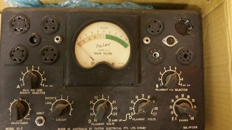 |
|
|
Return to top of page · Post #: 4 · Written at 10:04:51 AM on 27 January 2017.
|
|
|
|
Location: Wangaratta, VIC
Member since 21 February 2009 Member #: 438 Postcount: 5724 |
|
Photo received: Message sent. |
|
|
Return to top of page · Post #: 5 · Written at 7:51:54 PM on 27 January 2017.
|
|
|
|
Location: Latham, ACT
Member since 21 February 2015 Member #: 1705 Postcount: 2241 |
|
I can see what you mean about the miniature socket. It certainly looks out of place . I have studied it a bit and can see that it would be fairly easy to use. I downloaded a few user manuals last night and could easily pick up the jist of whats happening. |
|
|
Return to top of page · Post #: 6 · Written at 12:24:40 AM on 28 January 2017.
|
|
|
|
Location: Wangaratta, VIC
Member since 21 February 2009 Member #: 438 Postcount: 5724 |
|
It obviously pre-dates B9A but that 7 pin miniature does look ruthless and ruins the design symmetry (aesthetics) |
|
|
Return to top of page · Post #: 7 · Written at 1:19:28 AM on 28 January 2017.
|
|

|
Location: Sydney, NSW
Member since 28 January 2011 Member #: 823 Postcount: 6956 |
|
that 7 pin miniature does look ruthless and ruins the design symmetry (aesthetics) |
|
|
Return to top of page · Post #: 8 · Written at 2:11:46 AM on 28 January 2017.
|
|
|
|
Location: Latham, ACT
Member since 21 February 2015 Member #: 1705 Postcount: 2241 |
|
What are the two silver sockets ( one either side of the meter ) am I guessing correctly that they are for the top caps or is it something else? |
|
|
Return to top of page · Post #: 9 · Written at 9:18:52 AM on 28 January 2017.
|
|
|
|
Location: Wangaratta, VIC
Member since 21 February 2009 Member #: 438 Postcount: 5724 |
|
That's the problem with that extroverted socket, it draws the eye straight to it. |
|
|
Return to top of page · Post #: 10 · Written at 11:59:48 AM on 28 January 2017.
|
|
|
|
Location: Darlington, WA
Member since 30 March 2016 Member #: 1897 Postcount: 198 |
|
Is there a circuit available for the VCT Palec tester??. I would love to get hold of one. |
|
|
Return to top of page · Post #: 11 · Written at 12:04:50 PM on 28 January 2017.
|
|
|
|
Location: Wangaratta, VIC
Member since 21 February 2009 Member #: 438 Postcount: 5724 |
|
Do have: Original manual is about 12Meg. & there is a supplement plus other bits & pieces. |
|
|
Return to top of page · Post #: 12 · Written at 9:45:52 AM on 29 January 2017.
|
|
|
|
Location: Wangaratta, VIC
Member since 21 February 2009 Member #: 438 Postcount: 5724 |
|
Info sent, I do love the genius in only having pretty much all black & purple wires in mine, doesn't that make wire tracing fun. |
|
|
Return to top of page · Post #: 13 · Written at 12:44:51 PM on 29 January 2017.
|
|
|
|
Location: Darlington, WA
Member since 30 March 2016 Member #: 1897 Postcount: 198 |
|
Thanks Marcc, |
|
|
« Back ·
1 ·
Next »
|
|
|
You need to be a member to post comments on this forum.
|
|
 225V) Paper cap (HV) test (Neon flash method).
Sign In
Vintage Radio and Television is proudly brought to you by an era where things were built with pride and made to last.
DISCLAIMER: Valve radios and televisions contain voltages that can deliver lethal shocks. You should not attempt to work on a valve radio or other electrical appliances unless you know exactly what you are doing and have gained some experience with electronics and working around high voltages. The owner, administrators and staff of Vintage Radio & Television will accept no liability for any damage, injury or loss of life that comes as a result of your use or mis-use of information on this website. Please read our Safety Warning before using this website.
WARNING: Under no circumstances should you ever apply power to a vintage radio, television or other electrical appliance you have acquired without first having it checked and serviced by an experienced person. Also, at no time should any appliance be connected to an electricity supply if the power cord is damaged. If in doubt, do not apply power.
Shintara - Keepin' It Real · VileSilencer - Maintain The Rage