
General Discussion
Forum home - Go back to General discussion
|
Mystery Astor?
|
|
|
« Back ·
1 ·
Next »
|
|
|
Return to top of page · Post #: 1 · Written at 12:26:01 AM on 28 September 2016.
|
|
|
|
Location: Clare, SA
Member since 27 March 2016 Member #: 1894 Postcount: 513 |
|
A friend who saw my radio collection on facebook, gave me this absolute gem, which belonged to her hubby's grandfather, on condition, I take a video of it working for him. 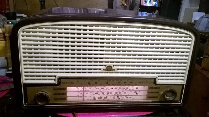 |
|
|
Return to top of page · Post #: 2 · Written at 1:01:36 AM on 28 September 2016.
|
|

|
Location: Sydney, NSW
Member since 28 January 2011 Member #: 823 Postcount: 6956 |
|
Photos? |
|
|
Return to top of page · Post #: 3 · Written at 1:27:06 AM on 28 September 2016.
|
|

|
Location: Wangaratta, VIC
Member since 21 February 2009 Member #: 438 Postcount: 5720 |
|
Yes to Photo's. I consider it to be an exercise in poor methodology and a poor use of time to go through a radio and replace the old wax paper caps & not make a decent effort to check the resistors. |
|
|
Return to top of page · Post #: 4 · Written at 3:25:20 AM on 28 September 2016.
|
|

|
Location: Melbourne, VIC
Member since 20 September 2011 Member #: 1009 Postcount: 1263 |
|
Post war Astors are notorious for perished rubber-coated wiring. Sometimes you can get away with sleeving the wires with heatshrink. |
|
|
Return to top of page · Post #: 5 · Written at 7:15:42 PM on 28 September 2016.
|
|
|
|
Location: Sydney, NSW
Member since 28 January 2011 Member #: 823 Postcount: 6956 |
|
Photo looks like model NS of 1951 with 6U7G, 6J8GA (or X61M), 6U7G, 6AV6, 6V6GT, 5Y3GT. |
|
|
Return to top of page · Post #: 6 · Written at 8:02:55 PM on 28 September 2016.
|
|

|
Location: Hill Top, NSW
Member since 18 September 2015 Member #: 1801 Postcount: 2256 |
|
Those Astors can be the very devil to get apart. The brown ring behind the knobs has to be undone and they can get stuck, and break easily. The dial lamps are in a spring that refuses to let the globe get removed without destroying both the globe and the spring. And so on. I detest them. |
|
|
Return to top of page · Post #: 7 · Written at 3:05:07 PM on 29 September 2016.
|
|
|
|
Location: Clare, SA
Member since 27 March 2016 Member #: 1894 Postcount: 513 |
|
Yes I noticed several different "innards" in ones I found pictures of trawling the net. Truthfully I admit I did just go for the lazy man's fix, hoping the resistors would be ok... Your not kidding about those brown bakelite screws behind the knobs, I managed fortunately to get them apart without any destruction, and was wondering what would be a suitable lubricant, I could put on the thread which would keep them easily removeable, I'm afraid to use grease etc in case it reacts with the bakelite... The dial lamps all work well, that's one good thing! Will post valve lineup as soon as I have another go at it, which will be soon. Just had a huge storm here phone lines are down, so will be swamped with RAA work (callouts) once the phones are back up and running! It truly is a lovely looking radio! |
|
|
Return to top of page · Post #: 8 · Written at 5:26:22 PM on 29 September 2016.
|
|

|
Administrator
Location: Naremburn, NSW
Member since 15 November 2005 Member #: 1 Postcount: 7633 |
|
Not much will hurt Bakelite though I think silicon spray will be a better bet. When it dries it doesn't leave any residue but when grease dries it just cakes things up. ‾‾‾‾‾‾‾‾‾‾‾‾‾‾‾‾‾‾‾‾‾‾‾‾‾‾‾‾‾‾‾‾‾‾‾‾‾‾‾‾‾‾‾‾‾‾‾‾‾‾‾‾‾‾‾‾‾‾‾‾‾‾‾‾‾‾‾‾ A valve a day keeps the transistor away... |
|
|
Return to top of page · Post #: 9 · Written at 7:59:27 PM on 29 September 2016.
|
|
|
|
Location: Clare, SA
Member since 27 March 2016 Member #: 1894 Postcount: 513 |
|
Thank's Brad, Silicone spray is good stuff, we have in workshop! There's rubber grease but grease does run and cake up over time. |
|
|
Return to top of page · Post #: 10 · Written at 6:47:02 PM on 1 October 2016.
|
|
|
|
Location: Clare, SA
Member since 27 March 2016 Member #: 1894 Postcount: 513 |
|
Ok it's got NJ 2733 stamped on the chassis, I can confirm the valves are: 5Y3GT, 6V6GT/G, 6G8G, 6A8G So now I'll check out Kev Chant for a schematic, so I can do the resistors and follow the wiring and make sure everything goes where it should! |
|
|
Return to top of page · Post #: 11 · Written at 1:32:38 PM on 3 October 2016.
|
|
|
|
Location: Clare, SA
Member since 27 March 2016 Member #: 1894 Postcount: 513 |
|
Ok I have replaced all of the resistors around the 6V6GT, these were all out of spec, but not too badly, the 50k was about 59, a 60k about 65, so yes, a bit on the high side, I did all of the ones around the volume pot, after that the ones I checked were in spec, I havn't checked every single one around the coils, as yet, but what I have by and large are fine, but still nothing out the speaker but a faint hum, regardless of volume, strangely whilst turning the tuning knob, the radio I was listening to while working on it started making "Cartoon radio noises" (If you know what I mean) at a certain spot when turning the knob. I have known good radio to do this when tuning another good radio in the same room as they arrect each other, so I'm guessing that this suggests the radio is working ok, and that the speaker transformer primary is in fact open circuit. In any case I have ordered another from Canada, check out the following link: |
|
|
Return to top of page · Post #: 12 · Written at 3:12:47 PM on 4 October 2016.
|
|
|
|
Location: Harston, VIC
Member since 28 February 2009 Member #: 442 Postcount: 145 |
|
G'day Jamie, |
|
|
Return to top of page · Post #: 13 · Written at 10:27:10 PM on 4 October 2016.
|
|
|
|
Location: Clare, SA
Member since 27 March 2016 Member #: 1894 Postcount: 513 |
|
Thanks Graham, you understand what I mean by "cartoon" noise lol. Yes I have a schematic, which I have been using to trace the circuit and test and replace resistors, however I am sure I have got all of the bad ones fixed and done all of the caps, so I'm stumped if it's not the speaker transformer? Maybe a valve has failed? Voltages seem right everywhere they are supposed to be... |
|
|
Return to top of page · Post #: 14 · Written at 10:32:31 PM on 4 October 2016.
|
|
|
|
Location: Clare, SA
Member since 27 March 2016 Member #: 1894 Postcount: 513 |
|
I'll try that screwdriver trick, next time I get to pull it apart, so long as I don't get a boot from it! I suppose the volume pot is a resistor it'self which my have failed too! Cheers Graham! |
|
|
Return to top of page · Post #: 15 · Written at 12:18:10 AM on 9 October 2016.
|
|
|
|
Location: Clare, SA
Member since 27 March 2016 Member #: 1894 Postcount: 513 |
|
Finally got this beauty working, seems some clown forgot to replace a wire connecting pin 6 of the 6A8G to pin 4 of the 6B8G, (sheepish expression) after studying the schematic for hours and scratching my head checking voltages etc. I discovered and corrected my error, with wonderful results! Yay, first one I have not only replaced all of the caps, but half of the resistors too!!! |
|
|
« Back ·
1 ·
Next »
|
|
|
You need to be a member to post comments on this forum.
|
|
Sign In
Vintage Radio and Television is proudly brought to you by an era where things were built with pride and made to last.
DISCLAIMER: Valve radios and televisions contain voltages that can deliver lethal shocks. You should not attempt to work on a valve radio or other electrical appliances unless you know exactly what you are doing and have gained some experience with electronics and working around high voltages. The owner, administrators and staff of Vintage Radio & Television will accept no liability for any damage, injury or loss of life that comes as a result of your use or mis-use of information on this website. Please read our Safety Warning before using this website.
WARNING: Under no circumstances should you ever apply power to a vintage radio, television or other electrical appliance you have acquired without first having it checked and serviced by an experienced person. Also, at no time should any appliance be connected to an electricity supply if the power cord is damaged. If in doubt, do not apply power.
Shintara - Keepin' It Real · VileSilencer - Maintain The Rage