
General Discussion
Forum home - Go back to General discussion
|
New member needs circuit
|
|
|
« Back ·
1 ·
Next »
|
|
|
Return to top of page · Post #: 1 · Written at 8:49:07 PM on 31 July 2016.
|
|

|
Location: Hobart, TAS
Member since 31 July 2016 Member #: 1959 Postcount: 605 |
|
Hello radio people, |
|
|
Return to top of page · Post #: 2 · Written at 10:35:58 PM on 31 July 2016.
|
|

|
Location: Sydney, NSW
Member since 28 January 2011 Member #: 823 Postcount: 6956 |
|
If you unhide your email address (use Control Panel) I'll send you the schematic and notes. |
|
|
Return to top of page · Post #: 3 · Written at 8:46:05 AM on 1 August 2016.
|
|
|
|
Location: Hobart, TAS
Member since 31 July 2016 Member #: 1959 Postcount: 605 |
|
Thank you, I think I have successfully unhide the address. |
|
|
Return to top of page · Post #: 4 · Written at 11:25:22 AM on 1 August 2016.
|
|

|
Location: Perth, WA
Member since 19 November 2008 Member #: 381 Postcount: 240 |
|
I'll get Brad to upload them so they are available for all in the future. |
|
|
Return to top of page · Post #: 5 · Written at 1:45:32 PM on 1 August 2016.
|
|
|
|
Location: Sydney, NSW
Member since 28 January 2011 Member #: 823 Postcount: 6956 |
|
Okay, sent. |
|
|
Return to top of page · Post #: 6 · Written at 7:59:16 PM on 1 August 2016.
|
|
|
|
Location: Hobart, TAS
Member since 31 July 2016 Member #: 1959 Postcount: 605 |
|
Received all OK, its great to get some solder fumes back in the workshop. |
|
|
Return to top of page · Post #: 7 · Written at 11:02:16 PM on 1 August 2016.
|
|

|
Administrator
Location: Naremburn, NSW
Member since 15 November 2005 Member #: 1 Postcount: 7633 |
|
Files uploaded to Post 4. ‾‾‾‾‾‾‾‾‾‾‾‾‾‾‾‾‾‾‾‾‾‾‾‾‾‾‾‾‾‾‾‾‾‾‾‾‾‾‾‾‾‾‾‾‾‾‾‾‾‾‾‾‾‾‾‾‾‾‾‾‾‾‾‾‾‾‾‾ A valve a day keeps the transistor away... |
|
|
Return to top of page · Post #: 8 · Written at 5:17:06 PM on 23 October 2016.
|
|
|
|
Location: Hobart, TAS
Member since 31 July 2016 Member #: 1959 Postcount: 605 |
|
Well this Monarch has finally come off the assembly line. 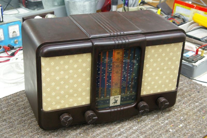 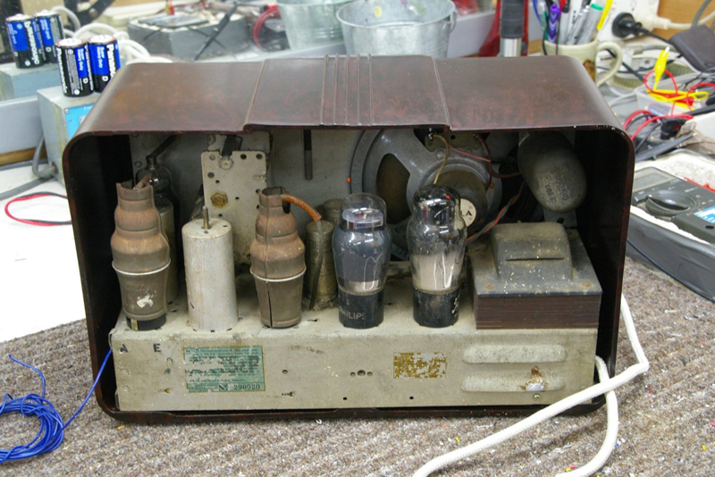 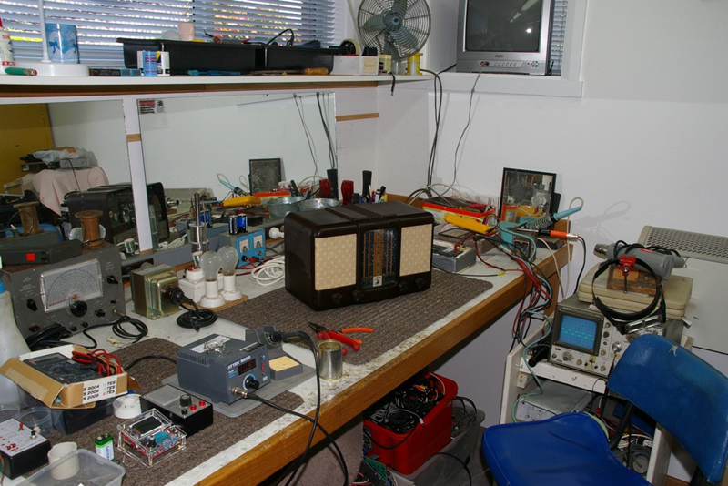 |
|
|
Return to top of page · Post #: 9 · Written at 8:45:32 PM on 25 October 2016.
|
|
|
|
Administrator
Location: Naremburn, NSW
Member since 15 November 2005 Member #: 1 Postcount: 7633 |
|
Photos uploaded to Post 8. ‾‾‾‾‾‾‾‾‾‾‾‾‾‾‾‾‾‾‾‾‾‾‾‾‾‾‾‾‾‾‾‾‾‾‾‾‾‾‾‾‾‾‾‾‾‾‾‾‾‾‾‾‾‾‾‾‾‾‾‾‾‾‾‾‾‾‾‾ A valve a day keeps the transistor away... |
|
|
Return to top of page · Post #: 10 · Written at 8:50:11 PM on 25 October 2016.
|
|
|
|
Location: Sydney, NSW
Member since 28 January 2011 Member #: 823 Postcount: 6956 |
|
Good job. |
|
|
Return to top of page · Post #: 11 · Written at 9:33:31 PM on 25 October 2016.
|
|

|
Location: Wangaratta, VIC
Member since 21 February 2009 Member #: 438 Postcount: 5720 |
|
Not intending to be insulting: I think that should be all of them, depending on who built it. I have one here (surplus to requirements) that had "oil filled" caps in it: They are as bad as waxed paper. |
|
|
Return to top of page · Post #: 12 · Written at 8:51:13 AM on 26 October 2016.
|
|
|
|
Location: Hobart, TAS
Member since 31 July 2016 Member #: 1959 Postcount: 605 |
|
Yes the sig gen while not my most accurate bit of test equipment is still used. |
|
|
Return to top of page · Post #: 13 · Written at 9:23:42 PM on 26 October 2016.
|
|
|
|
Location: Wangaratta, VIC
Member since 21 February 2009 Member #: 438 Postcount: 5720 |
|
I would concur that these and their clones are not spectacular but at least they are reasonably stable, Even with a NOS set of valves the high frequency end can be unpredictable and I do wonder why they never used the universal widget valve 6BL8. That is a Triode Pentode frequency converter and were as common as dishwater. |
|
|
« Back ·
1 ·
Next »
|
|
|
You need to be a member to post comments on this forum.
|
|
 .
.Sign In
Vintage Radio and Television is proudly brought to you by an era where things were built with pride and made to last.
DISCLAIMER: Valve radios and televisions contain voltages that can deliver lethal shocks. You should not attempt to work on a valve radio or other electrical appliances unless you know exactly what you are doing and have gained some experience with electronics and working around high voltages. The owner, administrators and staff of Vintage Radio & Television will accept no liability for any damage, injury or loss of life that comes as a result of your use or mis-use of information on this website. Please read our Safety Warning before using this website.
WARNING: Under no circumstances should you ever apply power to a vintage radio, television or other electrical appliance you have acquired without first having it checked and serviced by an experienced person. Also, at no time should any appliance be connected to an electricity supply if the power cord is damaged. If in doubt, do not apply power.
Shintara - Keepin' It Real · VileSilencer - Maintain The Rage