
General Discussion
Forum home - Go back to General discussion
|
Help Identifying Radiogram please
|
|
|
Return to top of page · Post #: 16 · Written at 8:55:52 PM on 2 August 2016.
|
|

|
Location: Sydney, NSW
Member since 28 January 2011 Member #: 823 Postcount: 6689 |
|
I honestly think this might be too far gone to get back to working condition |
|
|
Return to top of page · Post #: 17 · Written at 9:08:51 PM on 2 August 2016.
|
|

|
Location: Wangaratta, VIC
Member since 21 February 2009 Member #: 438 Postcount: 5259 |
|
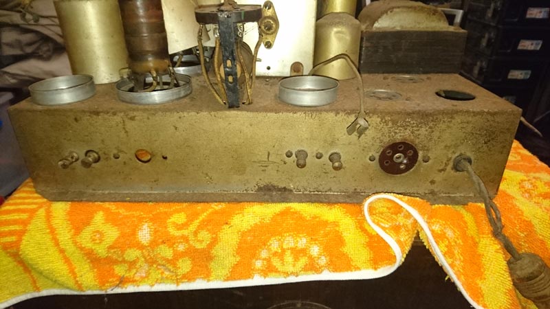
I assumed the speaker plug was at the back. It is likely electrodynamic and if so will have something like 2000 Ohms stamped on it. That will be the field coil resistance and another step. |
|
|
Return to top of page · Post #: 18 · Written at 10:49:27 PM on 2 August 2016.
|
|

|
Administrator
Location: Naremburn, NSW
Member since 15 November 2005 Member #: 1 Postcount: 7307 |
|
Photos uploaded to Post 15. ‾‾‾‾‾‾‾‾‾‾‾‾‾‾‾‾‾‾‾‾‾‾‾‾‾‾‾‾‾‾‾‾‾‾‾‾‾‾‾‾‾‾‾‾‾‾‾‾‾‾‾‾‾‾‾‾‾‾‾‾‾‾‾‾‾‾‾‾ A valve a day keeps the transistor away... |
|
|
Return to top of page · Post #: 19 · Written at 11:18:36 PM on 2 August 2016.
|
|
|
|
Location: Sydney, NSW
Member since 28 January 2011 Member #: 823 Postcount: 6689 |
|
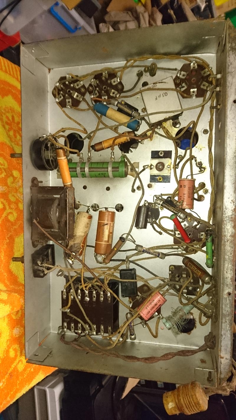
Once again: as per post #5 and #12, what we are seeking are photos of the rear and underside of the chassis. |
|
|
Return to top of page · Post #: 20 · Written at 8:08:16 AM on 3 August 2016.
|
|

|
Location: Latham, ACT
Member since 21 February 2015 Member #: 1705 Postcount: 2158 |
|
We need to see under the radio chassis |
|
|
Return to top of page · Post #: 21 · Written at 12:27:28 PM on 3 August 2016.
|
|

|
Location: Hill Top, NSW
Member since 18 September 2015 Member #: 1801 Postcount: 2017 |
|
Now we have photos (of sorts), it can be seen there are 6 valves, so it may be the same or similar to one of my wooden mysteries. That one has 57, 58, 57, 2A6, 2A5, 80 so I'd expect a very similar line-up for this radio. |
|
|
Return to top of page · Post #: 22 · Written at 7:05:09 PM on 3 August 2016.
|
|
|
|
Location: Latham, ACT
Member since 21 February 2015 Member #: 1705 Postcount: 2158 |
|
What about under the chassis. Sorry this one came up twice , I wasn't being rude but I was having trouble with my tablet . |
|
|
Return to top of page · Post #: 23 · Written at 7:14:55 PM on 3 August 2016.
|
|
|
|
Location: Maitland, NSW
Member since 16 May 2014 Member #: 1574 Postcount: 19 |
|
  |
|
|
Return to top of page · Post #: 24 · Written at 12:15:22 AM on 5 August 2016.
|
|
|
|
Administrator
Location: Naremburn, NSW
Member since 15 November 2005 Member #: 1 Postcount: 7307 |
|
Photos uploaded to Post 23. ‾‾‾‾‾‾‾‾‾‾‾‾‾‾‾‾‾‾‾‾‾‾‾‾‾‾‾‾‾‾‾‾‾‾‾‾‾‾‾‾‾‾‾‾‾‾‾‾‾‾‾‾‾‾‾‾‾‾‾‾‾‾‾‾‾‾‾‾ A valve a day keeps the transistor away... |
|
|
Return to top of page · Post #: 25 · Written at 1:03:44 AM on 5 August 2016.
|
|
|
|
Location: Sydney, NSW
Member since 28 January 2011 Member #: 823 Postcount: 6689 |
|
Wrong photos? They seem to relate to Unknown Wooden Radio #4. |
|
|
Return to top of page · Post #: 26 · Written at 1:25:26 AM on 5 August 2016.
|
|
|
|
Administrator
Location: Naremburn, NSW
Member since 15 November 2005 Member #: 1 Postcount: 7307 |
|
They were indeed the wrong photos. It's taken more than ten years for the naming convention I use to permit a file to be over-written - amazing. Correct photos have been renamed slightly. ‾‾‾‾‾‾‾‾‾‾‾‾‾‾‾‾‾‾‾‾‾‾‾‾‾‾‾‾‾‾‾‾‾‾‾‾‾‾‾‾‾‾‾‾‾‾‾‾‾‾‾‾‾‾‾‾‾‾‾‾‾‾‾‾‾‾‾‾ A valve a day keeps the transistor away... |
|
|
Return to top of page · Post #: 27 · Written at 1:47:05 AM on 5 August 2016.
|
|
|
|
Location: Sydney, NSW
Member since 28 January 2011 Member #: 823 Postcount: 6689 |
|
Okay, the very first thing that needs to be done is to cut off that mains cord. It's lethal. (Note the bayonet type plug -- power points were rare in houses back in the day so appliances were plugged into table lamps or light fittings.) |
|
|
Return to top of page · Post #: 28 · Written at 11:59:52 AM on 5 August 2016.
|
|
|
|
Location: Hill Top, NSW
Member since 18 September 2015 Member #: 1801 Postcount: 2017 |
|
What GTC said. |
|
|
Return to top of page · Post #: 29 · Written at 7:13:24 PM on 5 August 2016.
|
|
|
|
Location: Maitland, NSW
Member since 16 May 2014 Member #: 1574 Postcount: 19 |
|
Thanks for your encouraging words guys, perhaps it is worth restoring. |
|
|
Return to top of page · Post #: 30 · Written at 8:44:38 PM on 5 August 2016.
|
|
|
|
Location: Wangaratta, VIC
Member since 21 February 2009 Member #: 438 Postcount: 5259 |
|
The spider is actually perceived by many as the WEB browser. It would be a wonderful idea to remember that when you fire a flashgun at a reflective surface, you may as well fire it at a mirror. in a manual camera of old or where there is an adjustment (compensator) on a new camera white wedding cakes were always about 5 stops down on the flash setting. If the flash has no diffuser, and most on board ones don't stick some white tissue over it & don't stand front on. It is pointless if we cannot read the numbers. |
|
|
You need to be a member to post comments on this forum.
|
|
 GTC and
 Sign In
Vintage Radio and Television is proudly brought to you by an era where things were built with pride and made to last.
DISCLAIMER: Valve radios and televisions contain voltages that can deliver lethal shocks. You should not attempt to work on a valve radio or other electrical appliances unless you know exactly what you are doing and have gained some experience with electronics and working around high voltages. The owner, administrators and staff of Vintage Radio & Television will accept no liability for any damage, injury or loss of life that comes as a result of your use or mis-use of information on this website. Please read our Safety Warning before using this website.
WARNING: Under no circumstances should you ever apply power to a vintage radio, television or other electrical appliance you have acquired without first having it checked and serviced by an experienced person. Also, at no time should any appliance be connected to an electricity supply if the power cord is damaged. If in doubt, do not apply power.
Shintara - Keepin' It Real · VileSilencer - Maintain The Rage