
General Discussion
Forum home - Go back to General discussion
|
Vibrator Unit for AWA 608T
|
|
|
« Back ·
1 ·
Next »
|
|
|
Return to top of page · Post #: 1 · Written at 6:21:40 PM on 26 March 2016.
|
|

|
Location: Latham, ACT
Member since 21 February 2015 Member #: 1705 Postcount: 2236 |
|
I managed to spend a little time these last two days rebuilding the wiring loom for the Vibrator and totally rebuilding the Vibrator unit. I have sent some pictures and the difference between the old components and the new are chalk and cheese. 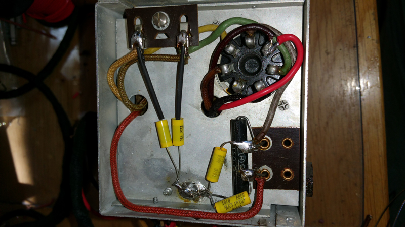 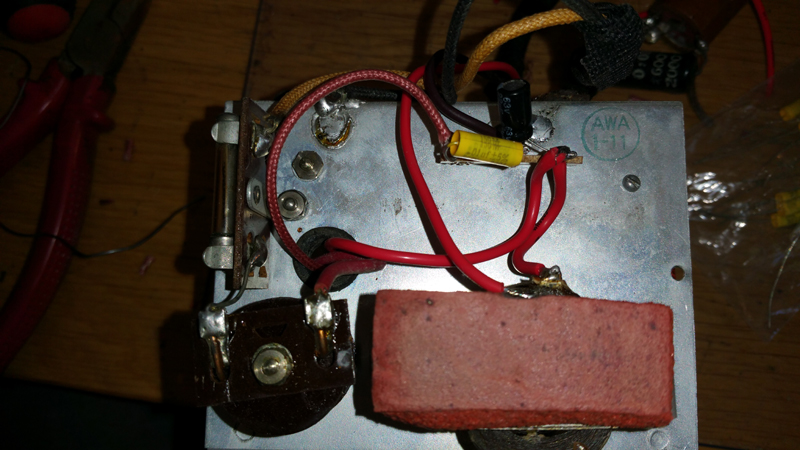 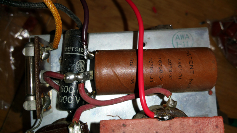 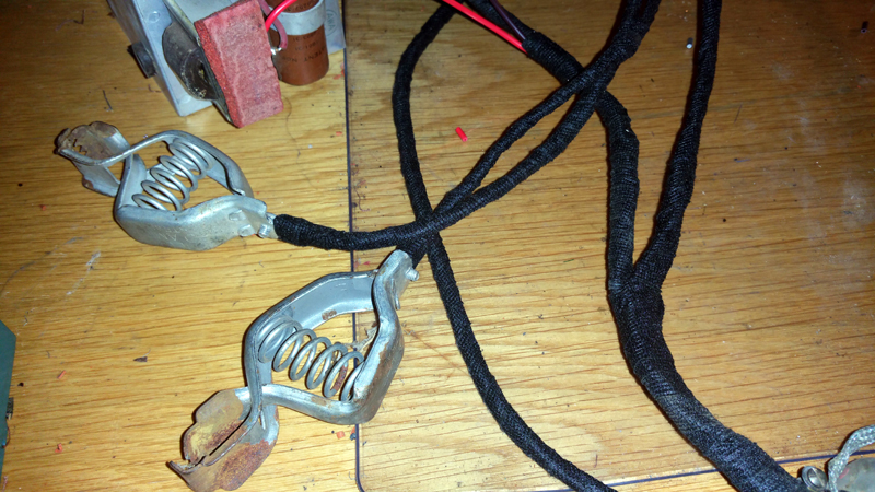 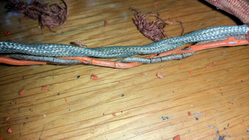 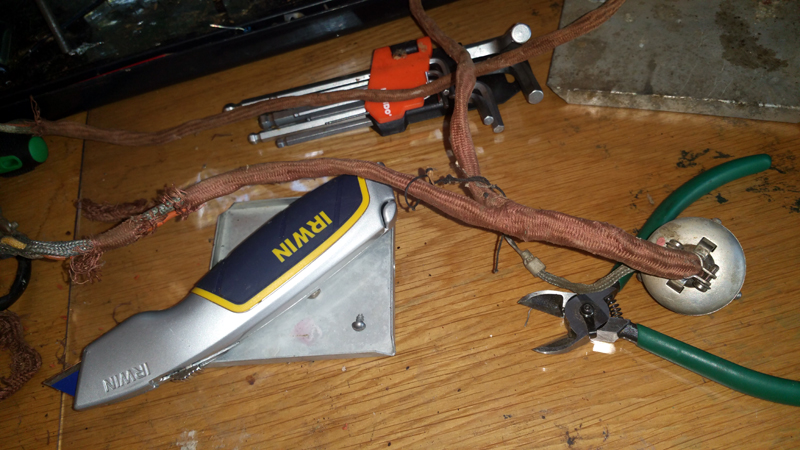 |
|
|
Return to top of page · Post #: 2 · Written at 5:59:53 AM on 30 March 2016.
|
|
|
|
Location: Latham, ACT
Member since 21 February 2015 Member #: 1705 Postcount: 2236 |
|
What I did in the bottom three photos was rewire the old wiring loom. As a assistant tech in my days at Telecom in the early eighties I used to build quite large wiring forms for the relay sets in use at the Tamworth exchange so making this one was a piece of cake and the new cotton tape really makes it look good. I have not tested the vibrator set yet but it looks like that will be happening this week as I have a few nights off, the third and the second photo are of the side of the vibrator unit where I have replaced a 20μF / 200 volt electro and a .100μF cap with their modern day equivalent. All of a sudden there is a lot of space. |
|
|
Return to top of page · Post #: 3 · Written at 9:34:59 AM on 30 March 2016.
|
|

|
Location: Wangaratta, VIC
Member since 21 February 2009 Member #: 438 Postcount: 5720 |
|
Where in the electrics is that 12V Electrolytic? The vibrator & Kettering ignitions send back a lot of HV spikes which is why the transistorised jobs had a "Spark plate" and why I will not have a mobile phone charger in the cigarette lighter in my Ute when its running. |
|
|
Return to top of page · Post #: 4 · Written at 3:27:57 PM on 30 March 2016.
|
|
|
|
Location: Latham, ACT
Member since 21 February 2015 Member #: 1705 Postcount: 2236 |
|
It runs from a 4 volt battery. And the cap I replaced was clearly marked as 20MFD/200volt. Sorry Marcc my error must have been tired and mind numb I meant 200 volt lol. |
|
|
Return to top of page · Post #: 5 · Written at 7:32:28 PM on 8 April 2016.
|
|
|
|
Location: Bathurst, NSW
Member since 7 August 2008 Member #: 336 Postcount: 412 |
|
Looks a lot more tidy and should be much less hash with new caps. My Ferris M94 is of that era and runs excellently. |
|
|
Return to top of page · Post #: 6 · Written at 8:00:32 AM on 18 April 2016.
|
|
|
|
Location: Latham, ACT
Member since 21 February 2015 Member #: 1705 Postcount: 2236 |
|
Well people this baby has been tested and works like a new one. The only thing I have to be careful of is that I don't give it any more than 4 volts as this will easily blow the valves. I will be building a regulated 4 volt power supply for it. |
|
|
« Back ·
1 ·
Next »
|
|
|
You need to be a member to post comments on this forum.
|
|
Sign In
Vintage Radio and Television is proudly brought to you by an era where things were built with pride and made to last.
DISCLAIMER: Valve radios and televisions contain voltages that can deliver lethal shocks. You should not attempt to work on a valve radio or other electrical appliances unless you know exactly what you are doing and have gained some experience with electronics and working around high voltages. The owner, administrators and staff of Vintage Radio & Television will accept no liability for any damage, injury or loss of life that comes as a result of your use or mis-use of information on this website. Please read our Safety Warning before using this website.
WARNING: Under no circumstances should you ever apply power to a vintage radio, television or other electrical appliance you have acquired without first having it checked and serviced by an experienced person. Also, at no time should any appliance be connected to an electricity supply if the power cord is damaged. If in doubt, do not apply power.
Shintara - Keepin' It Real · VileSilencer - Maintain The Rage