
General Discussion
Forum home - Go back to General discussion
|
Fisk Radiola (or is it?)
|
|
|
Return to top of page · Post #: 76 · Written at 6:49:39 PM on 15 February 2025.
|
|

|
Administrator
Location: Naremburn, NSW
Member since 15 November 2005 Member #: 1 Postcount: 7580 |
|
Document in Post 1 has been updated. ‾‾‾‾‾‾‾‾‾‾‾‾‾‾‾‾‾‾‾‾‾‾‾‾‾‾‾‾‾‾‾‾‾‾‾‾‾‾‾‾‾‾‾‾‾‾‾‾‾‾‾‾‾‾‾‾‾‾‾‾‾‾‾‾‾‾‾‾ A valve a day keeps the transistor away... |
|
|
Return to top of page · Post #: 77 · Written at 7:16:27 PM on 15 February 2025.
|
|

|
Location: Hill Top, NSW
Member since 18 September 2015 Member #: 1801 Postcount: 2231 |
|
Just curious, I noticed in the diagram that the grid resistor on the 6BD7 is 1M ohm, usually it's 10M - is it really 1M ? |
|
|
Return to top of page · Post #: 78 · Written at 9:34:07 PM on 15 February 2025.
|
|

|
Location: Wangaratta, VIC
Member since 21 February 2009 Member #: 438 Postcount: 5650 |
|
In the absence of any other circuit at the time. The radio museum one linked is back biased |
|
|
Return to top of page · Post #: 79 · Written at 12:32:16 PM on 16 February 2025.
|
|
|
|
Location: Melbourne, VIC
Member since 21 January 2025 Member #: 2702 Postcount: 57 |
|
Robert, |
|
|
Return to top of page · Post #: 80 · Written at 6:27:19 PM on 16 February 2025.
|
|
|
|
Location: Hill Top, NSW
Member since 18 September 2015 Member #: 1801 Postcount: 2231 |
|
Hmm, if the audio is fine then probably leave it as is. You can replace it with a 10M if you want. |
|
|
Return to top of page · Post #: 81 · Written at 9:20:30 PM on 16 February 2025.
|
|
|
|
Location: Wangaratta, VIC
Member since 21 February 2009 Member #: 438 Postcount: 5650 |
|
As I fix there is a thing called inventory and that costs. So, one tends to stock 630V NP Caps for tube radios as that keeps the inventory down. |
|
|
Return to top of page · Post #: 82 · Written at 8:01:46 AM on 17 February 2025.
|
|
|
|
Location: NSW
Member since 10 June 2010 Member #: 681 Postcount: 1382 |
|
"With Plate resistors on detector first audio, they have an attrition rate. Believe it or not grid resistors, be they the grid leak, or the grid stopper also have an attrition rate, especially on 6V6. The grid resistors on horrid little 6AV6's are rarely good. " |
|
|
Return to top of page · Post #: 83 · Written at 11:23:34 AM on 17 February 2025.
|
|
|
|
Location: Melbourne, VIC
Member since 21 January 2025 Member #: 2702 Postcount: 57 |
|
Jaycar rate their 1W carbon resistors at 500V. At 65 cents for two, they are as cheap as chips. Are they suitable for use in valve radios? Assuming dissipation is below 1W of course. |
|
|
Return to top of page · Post #: 84 · Written at 8:08:43 AM on 21 February 2025.
|
|
|
|
Location: Melbourne, VIC
Member since 21 January 2025 Member #: 2702 Postcount: 57 |
|
I have finished my 455kHz AM modulator and used it to adjust the four IF transformer trimmer screws for maximum volume through the speaker. The IF section was already pretty well aligned. Only one trimmer gave an improvement. Reception is improved. |
|
|
Return to top of page · Post #: 85 · Written at 6:05:36 PM on 21 February 2025.
|
|
|
|
Location: Belrose, NSW
Member since 31 December 2015 Member #: 1844 Postcount: 2666 |
|
Hum sounds like normal to me. Don't worry about it "overworking" the 6M5, it will have no effect at all. |
|
|
Return to top of page · Post #: 86 · Written at 6:13:09 PM on 21 February 2025.
|
|
|
|
Location: Melbourne, VIC
Member since 21 January 2025 Member #: 2702 Postcount: 57 |
|
Thanks Ian. It may well be normal. My ears have been spolied by decades of HiFi. |
|
|
Return to top of page · Post #: 87 · Written at 11:30:28 AM on 5 March 2025.
|
|
|
|
Location: Melbourne, VIC
Member since 21 January 2025 Member #: 2702 Postcount: 57 |
|
I have finished the restoration. 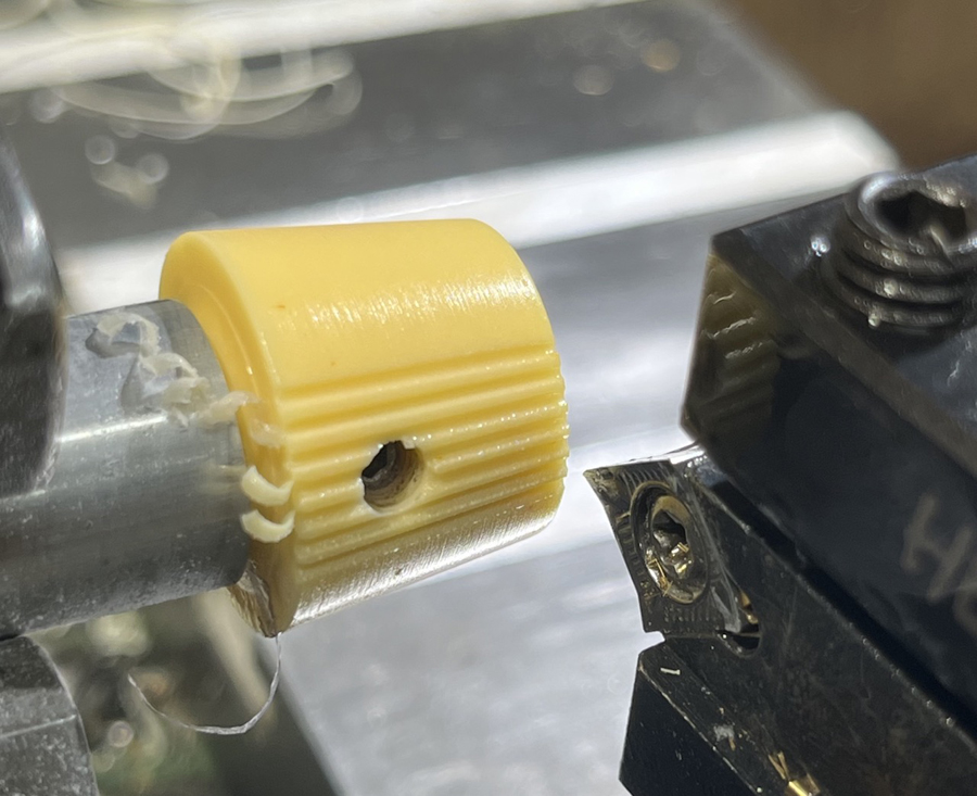 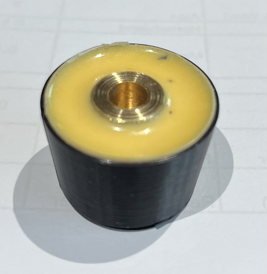 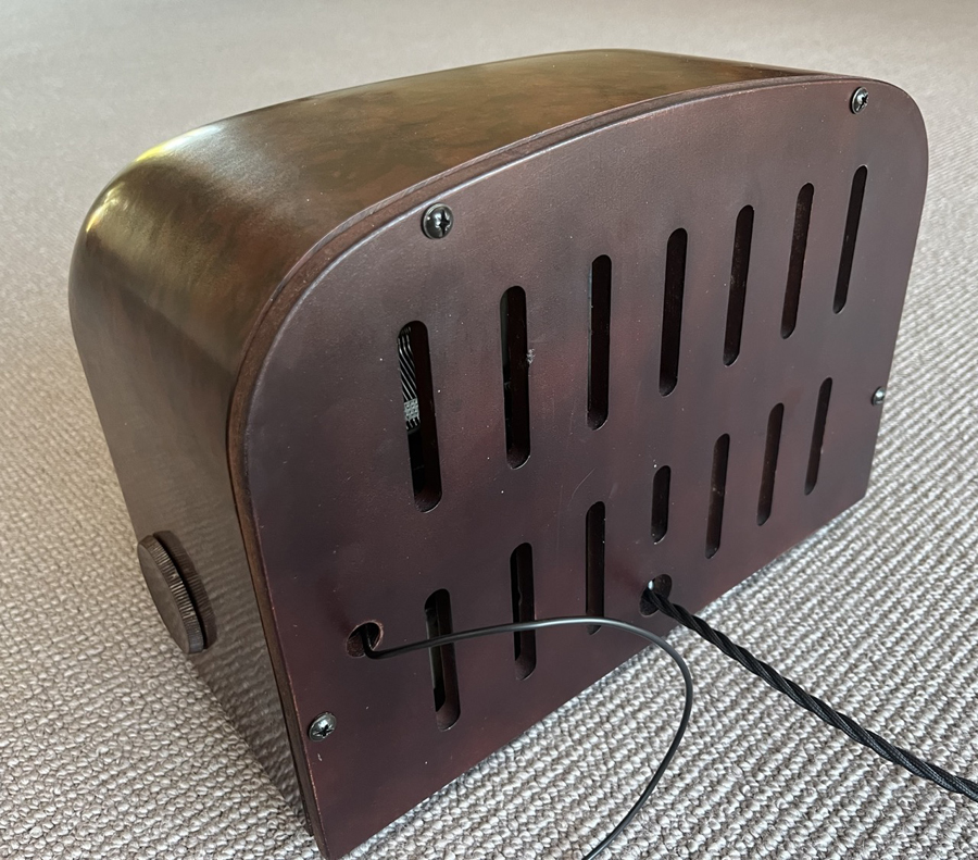 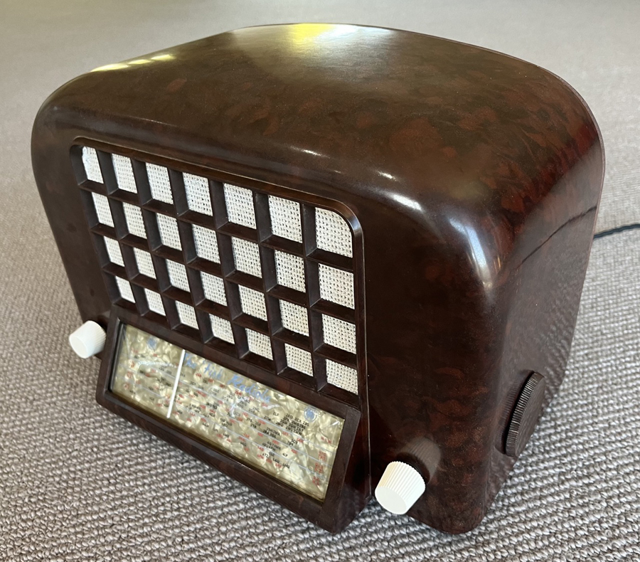  |
|
|
Return to top of page · Post #: 88 · Written at 3:52:00 PM on 5 March 2025.
|
|
|
|
Location: Toongabbie, NSW
Member since 19 November 2015 Member #: 1828 Postcount: 1385 |
|
Thats the sort of work I like to hear about. |
|
|
Return to top of page · Post #: 89 · Written at 9:00:42 PM on 6 March 2025.
|
|
|
|
Administrator
Location: Naremburn, NSW
Member since 15 November 2005 Member #: 1 Postcount: 7580 |
|
Photos uploaded to Post 87. ‾‾‾‾‾‾‾‾‾‾‾‾‾‾‾‾‾‾‾‾‾‾‾‾‾‾‾‾‾‾‾‾‾‾‾‾‾‾‾‾‾‾‾‾‾‾‾‾‾‾‾‾‾‾‾‾‾‾‾‾‾‾‾‾‾‾‾‾ A valve a day keeps the transistor away... |
|
|
Return to top of page · Post #: 90 · Written at 7:34:02 AM on 7 March 2025.
|
|
|
|
Location: Melbourne, VIC
Member since 21 January 2025 Member #: 2702 Postcount: 57 |
|
Fred, |
|
|
You need to be a member to post comments on this forum.
|
|
Sign In
Vintage Radio and Television is proudly brought to you by an era where things were built with pride and made to last.
DISCLAIMER: Valve radios and televisions contain voltages that can deliver lethal shocks. You should not attempt to work on a valve radio or other electrical appliances unless you know exactly what you are doing and have gained some experience with electronics and working around high voltages. The owner, administrators and staff of Vintage Radio & Television will accept no liability for any damage, injury or loss of life that comes as a result of your use or mis-use of information on this website. Please read our Safety Warning before using this website.
WARNING: Under no circumstances should you ever apply power to a vintage radio, television or other electrical appliance you have acquired without first having it checked and serviced by an experienced person. Also, at no time should any appliance be connected to an electricity supply if the power cord is damaged. If in doubt, do not apply power.
Shintara - Keepin' It Real · VileSilencer - Maintain The Rage