
General Discussion
Forum home - Go back to General discussion
|
The Basket Case Mullard 1110
|
|
|
Return to top of page · Post #: 16 · Written at 11:03:27 AM on 15 March 2015.
|
|

|
Location: Adelaide, SA
Member since 27 February 2010 Member #: 630 Postcount: 398 |
|
Hi All 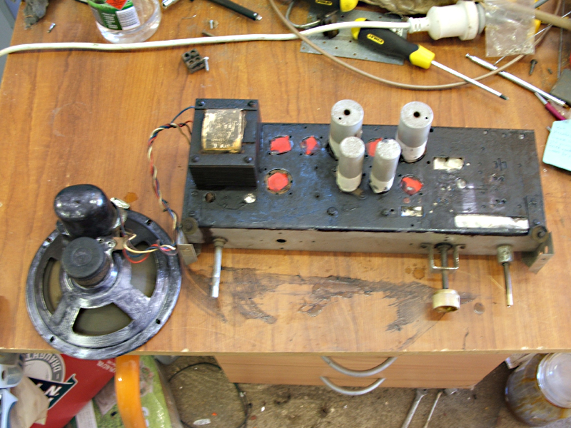   ‾‾‾‾‾‾‾‾‾‾‾‾‾‾‾‾‾‾‾‾‾‾‾‾‾‾‾‾‾‾‾‾‾‾‾‾‾‾‾‾‾‾‾‾‾‾‾‾‾‾‾‾‾‾‾‾‾‾‾‾‾‾‾‾‾‾‾‾ Valve radios, They just don't make them like they used to |
|
|
Return to top of page · Post #: 17 · Written at 10:52:12 AM on 18 April 2015.
|
|
|
|
Location: Adelaide, SA
Member since 27 February 2010 Member #: 630 Postcount: 398 |
|
Hi All   Another Update: I have had the set on test for about 24hrs and noticed that the sensitivity of it varied from time to time. I started the "Technical Tap" method just to see if that changed things. it showed around the IF cans and the 1st 6N8 that the sensitivity improved. I stated to isolate things by changing the 6N8 and found this when put on the tester varied its gain when tapped. So all up in this set I have changed 2 valves due to internal faults inside them. I guess after 50 odd years being bounced around from time to time the internal elements and connections weaken. ‾‾‾‾‾‾‾‾‾‾‾‾‾‾‾‾‾‾‾‾‾‾‾‾‾‾‾‾‾‾‾‾‾‾‾‾‾‾‾‾‾‾‾‾‾‾‾‾‾‾‾‾‾‾‾‾‾‾‾‾‾‾‾‾‾‾‾‾ Valve radios, They just don't make them like they used to |
|
|
Return to top of page · Post #: 18 · Written at 11:35:42 AM on 10 May 2015.
|
|
|
|
Location: Adelaide, SA
Member since 27 February 2010 Member #: 630 Postcount: 398 |
|
Hi All 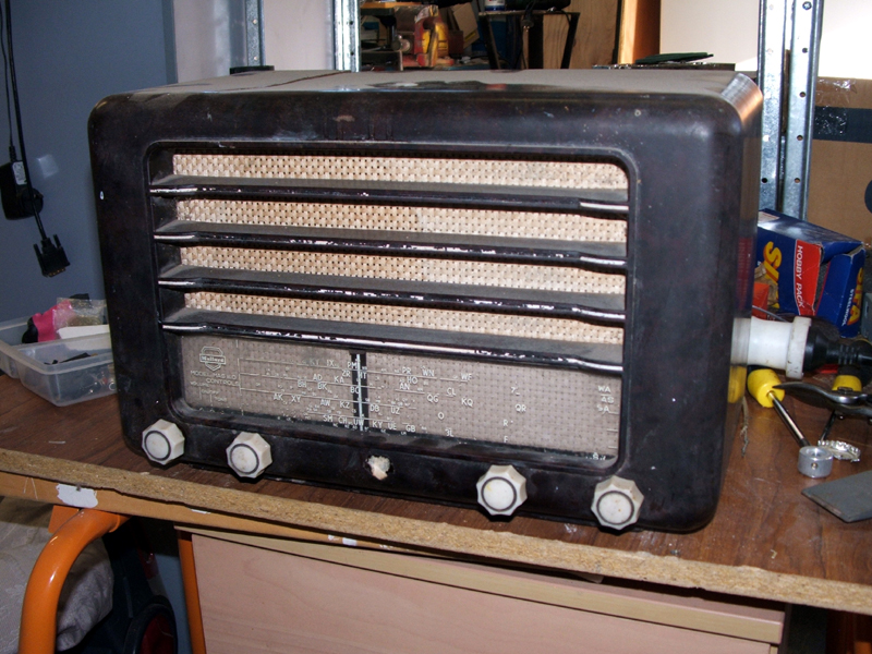 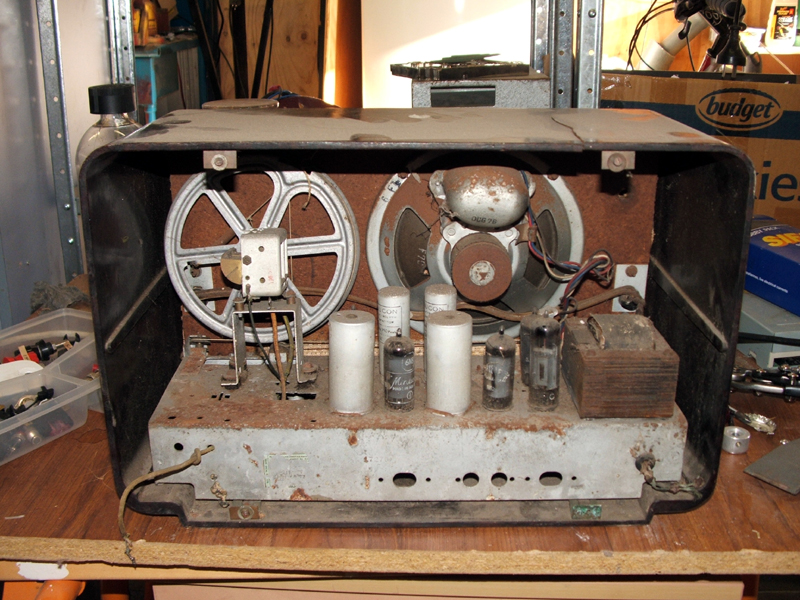 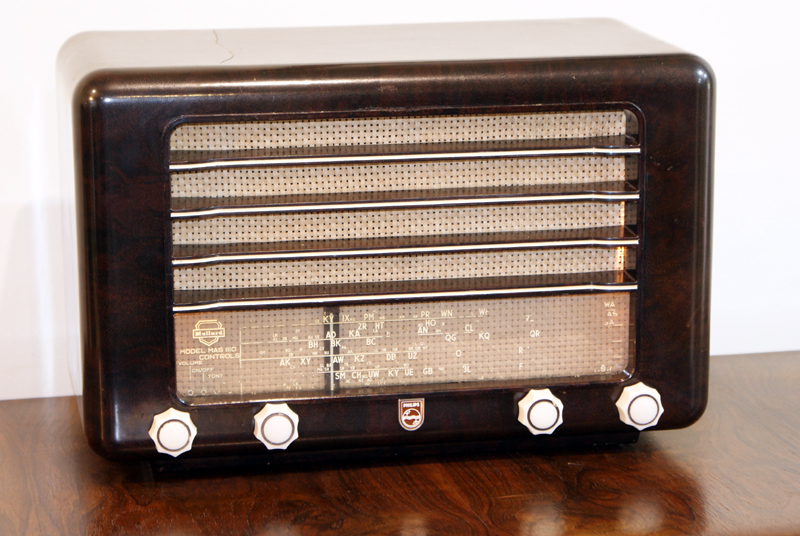 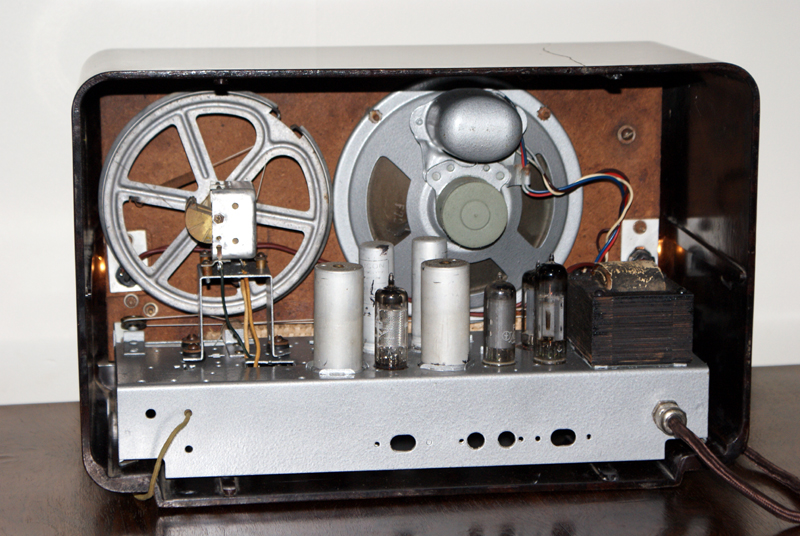 ‾‾‾‾‾‾‾‾‾‾‾‾‾‾‾‾‾‾‾‾‾‾‾‾‾‾‾‾‾‾‾‾‾‾‾‾‾‾‾‾‾‾‾‾‾‾‾‾‾‾‾‾‾‾‾‾‾‾‾‾‾‾‾‾‾‾‾‾ Valve radios, They just don't make them like they used to |
|
|
Return to top of page · Post #: 19 · Written at 8:47:11 PM on 12 May 2015.
|
|
|
|
Location: Devonport, TAS
Member since 26 March 2015 Member #: 1718 Postcount: 22 |
|
The hammer finish paint really comes up a treat! Good job |
|
|
Return to top of page · Post #: 20 · Written at 9:32:58 PM on 12 May 2015.
|
|

|
Location: Wangaratta, VIC
Member since 21 February 2009 Member #: 438 Postcount: 5711 |
|
You may actually be able to glue some awning cloth under the crack to hold it. A lot of that stuff is designed to be in the sun so will handle a bit of heat. On most cabinets I pad Araldite (not 5min) into the cloth before placing it onto the well cleaned surface. |
|
|
Return to top of page · Post #: 21 · Written at 9:46:18 AM on 13 May 2015.
|
|
|
|
Location: Calista, WA
Member since 1 April 2014 Member #: 1540 Postcount: 81 |
|
Dan, ‾‾‾‾‾‾‾‾‾‾‾‾‾‾‾‾‾‾‾‾‾‾‾‾‾‾‾‾‾‾‾‾‾‾‾‾‾‾‾‾‾‾‾‾‾‾‾‾‾‾‾‾‾‾‾‾‾‾‾‾‾‾‾‾‾‾‾‾ Baz VK6MU |
|
|
Return to top of page · Post #: 22 · Written at 12:22:36 PM on 13 May 2015.
|
|
|
|
Location: Adelaide, SA
Member since 27 February 2010 Member #: 630 Postcount: 398 |
|
Hi ‾‾‾‾‾‾‾‾‾‾‾‾‾‾‾‾‾‾‾‾‾‾‾‾‾‾‾‾‾‾‾‾‾‾‾‾‾‾‾‾‾‾‾‾‾‾‾‾‾‾‾‾‾‾‾‾‾‾‾‾‾‾‾‾‾‾‾‾ Valve radios, They just don't make them like they used to |
|
|
Return to top of page · Post #: 23 · Written at 10:08:43 PM on 15 May 2015.
|
|
|
|
Location: Canberra, ACT
Member since 23 August 2012 Member #: 1208 Postcount: 587 |
|
This looks identical internally to the 1950 Philips Radioplayer 123, only visible difference the dial glass and the grille (123 is vertical). I didn't notice pick-up terminals on the back, though. |
|
|
Return to top of page · Post #: 24 · Written at 11:52:56 PM on 15 May 2015.
|
|
|
|
Location: Wangaratta, VIC
Member since 21 February 2009 Member #: 438 Postcount: 5711 |
|
The cabinet of the 123L I sent in (1st page) is identical |
|
|
You need to be a member to post comments on this forum.
|
|
Sign In
Vintage Radio and Television is proudly brought to you by an era where things were built with pride and made to last.
DISCLAIMER: Valve radios and televisions contain voltages that can deliver lethal shocks. You should not attempt to work on a valve radio or other electrical appliances unless you know exactly what you are doing and have gained some experience with electronics and working around high voltages. The owner, administrators and staff of Vintage Radio & Television will accept no liability for any damage, injury or loss of life that comes as a result of your use or mis-use of information on this website. Please read our Safety Warning before using this website.
WARNING: Under no circumstances should you ever apply power to a vintage radio, television or other electrical appliance you have acquired without first having it checked and serviced by an experienced person. Also, at no time should any appliance be connected to an electricity supply if the power cord is damaged. If in doubt, do not apply power.
Shintara - Keepin' It Real · VileSilencer - Maintain The Rage