
General Discussion
Forum home - Go back to General discussion
|
Scharnberg Strauss model 41 circuit diagram
|
|
|
Return to top of page · Post #: 16 · Written at 7:47:25 PM on 20 July 2014.
|
|

|
Location: Wangaratta, VIC
Member since 21 February 2009 Member #: 438 Postcount: 5719 |
|
If it is not back biased it will have more parts as every valve other than the rectifier will have a cathode resistor and the one for EL3NG will be around 150 Ohms and 6V6 around 270 Ohms. |
|
|
Return to top of page · Post #: 17 · Written at 9:25:40 PM on 20 July 2014.
|
|
|
|
Location: Cameron Park, NSW
Member since 5 November 2010 Member #: 770 Postcount: 427 |
|
The blue set in the above link is from my collection and the valves are in the right holes. The difference is that mine uses a 5Y3G and a 6V6GT, whereas in Steve's set, the 5Y3 is a GT type and the output valve is a G type. |
|
|
Return to top of page · Post #: 18 · Written at 9:54:11 PM on 20 July 2014.
|
|
|
|
Location: Stanmore, NSW
Member since 6 July 2014 Member #: 1599 Postcount: 29 |
|
The two lower caps are marked "8MFD 600P.V" I'm assuming these are 8μF 600volt. The next larger one up is marked "10MFD 40P.V" all the others as you can see are marked .05 varying from 400 to 200v. I guess these can be replaced by 47μF caps say 450v? One is marked .005. |
|
|
Return to top of page · Post #: 19 · Written at 10:10:54 PM on 20 July 2014.
|
|

|
Location: Sydney, NSW
Member since 28 January 2011 Member #: 823 Postcount: 6952 |
|
Do you guys think it's worth doing? |
|
|
Return to top of page · Post #: 20 · Written at 11:22:12 PM on 20 July 2014.
|
|
|
|
Location: Wangaratta, VIC
Member since 21 February 2009 Member #: 438 Postcount: 5719 |
|
With the amount of corrosion, if you want it to look anything like pristine, you are going to have to strip the chassis and that will not take 5 minutes, nor will reassembly. |
|
|
Return to top of page · Post #: 21 · Written at 5:00:20 PM on 26 July 2014.
|
|
|
|
Location: Stanmore, NSW
Member since 6 July 2014 Member #: 1599 Postcount: 29 |
|
Ok thanks Marc. I think I'll just fix the cabinet and get the set to work as best as I can. I don't get a good reading on the large valve on the valve tester, but I'm using EL33 settings. The 5YGT rectifier looks good the 6A8G measures good and the EBF35 is good as well. I'll make a start on the caps. |
|
|
Return to top of page · Post #: 22 · Written at 7:27:17 PM on 27 July 2014.
|
|
|
|
Location: Wangaratta, VIC
Member since 21 February 2009 Member #: 438 Postcount: 5719 |
|
EL3N was replaced by EL33 according to Philips data. |
|
|
Return to top of page · Post #: 23 · Written at 10:00:20 AM on 28 July 2014.
|
|
|
|
Location: Stanmore, NSW
Member since 6 July 2014 Member #: 1599 Postcount: 29 |
|
Hi Guys, |
|
|
Return to top of page · Post #: 24 · Written at 4:07:35 PM on 28 July 2014.
|
|
|
|
Location: Cameron Park, NSW
Member since 5 November 2010 Member #: 770 Postcount: 427 |
|
While the pin connections are the same, bias and load figures are different, so not recommended for a permanent fix. Probably OK for a short time to test, but if you are going to make it permanent, make sure you adjust the bias to suit. |
|
|
Return to top of page · Post #: 25 · Written at 8:59:32 PM on 28 July 2014.
|
|

|
Location: Adelaide, SA
Member since 27 February 2010 Member #: 630 Postcount: 398 |
|
Hi Steve ‾‾‾‾‾‾‾‾‾‾‾‾‾‾‾‾‾‾‾‾‾‾‾‾‾‾‾‾‾‾‾‾‾‾‾‾‾‾‾‾‾‾‾‾‾‾‾‾‾‾‾‾‾‾‾‾‾‾‾‾‾‾‾‾‾‾‾‾ Valve radios, They just don't make them like they used to |
|
|
Return to top of page · Post #: 26 · Written at 10:29:39 PM on 28 July 2014.
|
|
|
|
Location: Stanmore, NSW
Member since 6 July 2014 Member #: 1599 Postcount: 29 |
|
Thanks Harold, maybe I'll just stick to getting the EL33. They are just much more expensive!! |
|
|
Return to top of page · Post #: 27 · Written at 1:42:10 AM on 29 July 2014.
|
|
|
|
Location: Wangaratta, VIC
Member since 21 February 2009 Member #: 438 Postcount: 5719 |
|
I would not get a new tube until such time as you have proven it faulty. |
|
|
Return to top of page · Post #: 28 · Written at 7:59:30 PM on 29 July 2014.
|
|
|
|
Location: Stanmore, NSW
Member since 6 July 2014 Member #: 1599 Postcount: 29 |
|
OK, thanks Marc. I'll open it up and have a look. The paper look up chart is a bit dodgy so I'll fix that as well if I can. Thank formal the advice. |
|
|
Return to top of page · Post #: 29 · Written at 10:07:55 AM on 30 July 2014.
|
|

|
Location: Melbourne, VIC
Member since 20 September 2011 Member #: 1009 Postcount: 1263 |
|
In Radio Days, Australian Bakelite Radios by Peter Sheridan & Ritchie Singer on page 152 there are three Scharnberg Strauss 41's. The next facing page (153) is the same radio, but branded Weldon. (Weldon York?) |
|
|
Return to top of page · Post #: 30 · Written at 7:59:35 PM on 13 August 2014.
|
|
|
|
Location: Stanmore, NSW
Member since 6 July 2014 Member #: 1599 Postcount: 29 |
|
Getting closer now. Got most of the caps. Cabinet is looking OK. Harold, it has a really weird station indicator, seams to run on the metal chassis. I'll put in a photo tomorrow if I can. It's quite rusty as well. 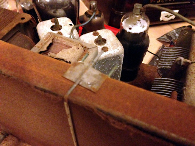 |
|
|
You need to be a member to post comments on this forum.
|
|

Sign In
Vintage Radio and Television is proudly brought to you by an era where things were built with pride and made to last.
DISCLAIMER: Valve radios and televisions contain voltages that can deliver lethal shocks. You should not attempt to work on a valve radio or other electrical appliances unless you know exactly what you are doing and have gained some experience with electronics and working around high voltages. The owner, administrators and staff of Vintage Radio & Television will accept no liability for any damage, injury or loss of life that comes as a result of your use or mis-use of information on this website. Please read our Safety Warning before using this website.
WARNING: Under no circumstances should you ever apply power to a vintage radio, television or other electrical appliance you have acquired without first having it checked and serviced by an experienced person. Also, at no time should any appliance be connected to an electricity supply if the power cord is damaged. If in doubt, do not apply power.
Shintara - Keepin' It Real · VileSilencer - Maintain The Rage