
General Discussion
Forum home - Go back to General discussion
|
Temperature of valves in a radio
|
|
|
Return to top of page · Post #: 16 · Written at 6:37:42 PM on 24 May 2014.
|
|
|
|
Location: Blue Mountains, NSW
Member since 10 March 2013 Member #: 1312 Postcount: 401 |
|
Changing R2 & R3 has put the screen voltage for the 6AN7 and 6N8 back in spec. The valves are now happier with increased current draw hence the higher bias voltage which makes the 6M5 happier as well, drawing more current and producing a bit more heat. Power valves in general and 6M5's in particular do run very hot although I have no idea of what a normal temperature would be or indeed any thing to measure it. If the B+ and other voltages are OK and it is genuinely running hot the only other thing I can think of is that its drawing grid current which I believe 6M5's are also noted for, though I think that would lower the plate voltage. Someone else might have some more ideas on this. |
|
|
Return to top of page · Post #: 17 · Written at 7:00:35 PM on 24 May 2014.
|
|

|
Location: Sydney, NSW
Member since 28 January 2011 Member #: 823 Postcount: 6956 |
|
I'm not sure that you have a problem. As was mentioned above, power output valves do run hot. |
|
|
Return to top of page · Post #: 18 · Written at 8:09:46 PM on 24 May 2014.
|
|

|
Location: Melbourne, VIC
Member since 20 September 2011 Member #: 1009 Postcount: 1263 |
|
I've found this notice from the Kriesler Manual of Technical Instructions regarding issues with faulty batches of 6M5's and how to solve them:- 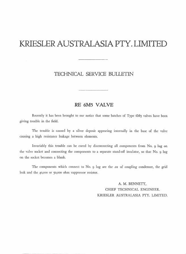 Click on image for PDF version I don't know if the Fleetwood/Philips sets use pin 9 on the 6M5 socket as a tie point for other components. If it does it may well be wise to follow the above advice. I think the 6M5's giving the most trouble are the earlier "Innoval" types. Innoval valves are distinct from normal miniature 9 pin valves as they have a flatter base. |
|
|
Return to top of page · Post #: 19 · Written at 8:23:30 PM on 24 May 2014.
|
|
|
|
Location: Melbourne, VIC
Member since 19 May 2014 Member #: 1577 Postcount: 101 |
|
Thanks Monochrome625 for the info. I checked the radio that pin 9 has nothing connected to it. |
|
|
Return to top of page · Post #: 20 · Written at 8:55:43 PM on 24 May 2014.
|
|
|
|
Location: Melbourne, VIC
Member since 19 May 2014 Member #: 1577 Postcount: 101 |
|
Yes, you are right. The base of the tube is kind of flat compared with 6V4's. |
|
|
Return to top of page · Post #: 21 · Written at 7:09:33 AM on 17 August 2014.
|
|
|
|
Location: Blue Mountains, NSW
Member since 10 March 2013 Member #: 1312 Postcount: 401 |
|
That technical bulletin is interesting . I've read in a couple of places that scratching between the pins can sometimes resolve the problem but if the silver migration is internal no amount of scratching will fix that! |
|
|
Return to top of page · Post #: 22 · Written at 11:42:29 AM on 17 August 2014.
|
|

|
Location: Wangaratta, VIC
Member since 21 February 2009 Member #: 438 Postcount: 5724 |
|
I did list the voltage & current for that valve, so if is is operating within specs & the plate is not red I do not see cause for panic. You may find that the rectifier is running at a similar temp. You could always measure the cathode current, but with back bias in the majority of cases, all of the cathode current passes through the back bias resistor. Therefore if the set is not running within the correct parameters the voltage across it will be wrong. |
|
|
You need to be a member to post comments on this forum.
|
|
Sign In
Vintage Radio and Television is proudly brought to you by an era where things were built with pride and made to last.
DISCLAIMER: Valve radios and televisions contain voltages that can deliver lethal shocks. You should not attempt to work on a valve radio or other electrical appliances unless you know exactly what you are doing and have gained some experience with electronics and working around high voltages. The owner, administrators and staff of Vintage Radio & Television will accept no liability for any damage, injury or loss of life that comes as a result of your use or mis-use of information on this website. Please read our Safety Warning before using this website.
WARNING: Under no circumstances should you ever apply power to a vintage radio, television or other electrical appliance you have acquired without first having it checked and serviced by an experienced person. Also, at no time should any appliance be connected to an electricity supply if the power cord is damaged. If in doubt, do not apply power.
Shintara - Keepin' It Real · VileSilencer - Maintain The Rage