
Vintage Telephones
Forum home - Go back to Vintage Telephones
|
Phone Ringer Circuit
|
|
|
Return to top of page · Post #: 16 · Written at 11:28:33 PM on 17 September 2015.
|
|

|
Location: Latham, ACT
Member since 21 February 2015 Member #: 1705 Postcount: 2154 |
|
I will tell you guys about a true to life complaint that telecom dealt with when I was working for them. This is quite Hilarious but totally true. A farmer rang and complained that his phone did not ring but he always knew when someone was giving him a call because his DOG WOULD BARK. |
|
|
Return to top of page · Post #: 17 · Written at 12:56:06 AM on 19 September 2015.
|
|
|
|
Location: Somewhere, USA
Member since 22 October 2013 Member #: 1437 Postcount: 896 |
|
Oh ok, I wonder if he put up more than the usual fight about getting chained to the fence. |
|
|
Return to top of page · Post #: 18 · Written at 2:17:43 AM on 19 September 2015.
|
|
|
|
Location: Latham, ACT
Member since 21 February 2015 Member #: 1705 Postcount: 2154 |
|
That is actually a true story . |
|
|
Return to top of page · Post #: 19 · Written at 1:14:11 AM on 22 September 2015.
|
|
|
|
Location: Somewhere, USA
Member since 22 October 2013 Member #: 1437 Postcount: 896 |
|
I don’t doubt it, apparently in the early days of Edison’s DC distribution, |
|
|
Return to top of page · Post #: 20 · Written at 3:00:47 PM on 25 September 2015.
|
|

|
Location: Canberra, ACT
Member since 24 April 2012 Member #: 1136 Postcount: 168 |
|
Inspired by Art I went back to the H-bridge circuit I had previously looked at and tried it in an emulator program (http://www.falstad.com/circuit/). 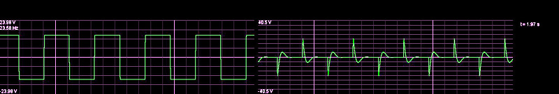 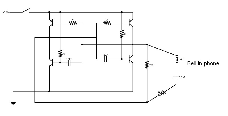 I'm not presently in a position to build the circuit but it would be interesting if someone (Art?) could try it to see if it actually worked. Andrew |
|
|
Return to top of page · Post #: 21 · Written at 11:34:12 PM on 26 September 2015.
|
|
|
|
Location: Somewhere, USA
Member since 22 October 2013 Member #: 1437 Postcount: 896 |
|
Hi Guys, |
|
|
Return to top of page · Post #: 22 · Written at 12:52:31 PM on 27 September 2015.
|
|
|
|
Location: Somewhere, USA
Member since 22 October 2013 Member #: 1437 Postcount: 896 |
|
Hi again Guys |
|
|
Return to top of page · Post #: 23 · Written at 7:13:05 PM on 27 September 2015.
|
|

|
Administrator
Location: Naremburn, NSW
Member since 15 November 2005 Member #: 1 Postcount: 7300 |
|
What I seem to remember is a longer ring first like this: Riiiiiiiiing..... ring..ring..... ring..ring..... ring..ring..... and so on. ‾‾‾‾‾‾‾‾‾‾‾‾‾‾‾‾‾‾‾‾‾‾‾‾‾‾‾‾‾‾‾‾‾‾‾‾‾‾‾‾‾‾‾‾‾‾‾‾‾‾‾‾‾‾‾‾‾‾‾‾‾‾‾‾‾‾‾‾ A valve a day keeps the transistor away... |
|
|
Return to top of page · Post #: 24 · Written at 11:12:06 PM on 27 September 2015.
|
|
|
|
Location: Somewhere, USA
Member since 22 October 2013 Member #: 1437 Postcount: 896 |
|
I’ll have another video up soon. It turns out more convoluted than I thought, |
|
|
Return to top of page · Post #: 25 · Written at 12:27:28 AM on 28 September 2015.
|
|

|
Location: Sydney, NSW
Member since 28 January 2011 Member #: 823 Postcount: 6686 |
|
I do think I’ll do a micro controller version as well for pic 16F628A |
|
|
Return to top of page · Post #: 26 · Written at 1:49:56 AM on 28 September 2015.
|
|
|
|
Location: Somewhere, USA
Member since 22 October 2013 Member #: 1437 Postcount: 896 |
|
Cool |
|
|
Return to top of page · Post #: 27 · Written at 2:18:16 AM on 28 September 2015.
|
|
|
|
Location: Somewhere, USA
Member since 22 October 2013 Member #: 1437 Postcount: 896 |
|
Relay, that principle will work. It will be automatically tracking the resonant frequency |
|
|
Return to top of page · Post #: 28 · Written at 10:52:44 PM on 6 October 2015.
|
|
|
|
Location: Canberra, ACT
Member since 24 April 2012 Member #: 1136 Postcount: 168 |
|
As previously mentioned back in the days of electro-mechanical ring generators small manual exchanges and some PAX installations often used a pole-changer which was a tuned relay or vibrator that ‘oscillated’ at about 16Hz and alternately switched 24–48V +/- to the line to give a square wave of 48-96V PP. A photo (courtesy of http://www.museumoftechnology.org.uk/) shows a pole-changer made by Siemens Bros c1920. 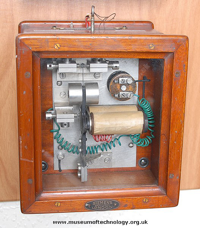 Larger exchanges had motor-generator that generated the 16-20Hz ring, the 33Hz (later 133Hz) Dial Tone, Ring Tone and the 400Hz tone that was used for Busy and NU. Cams geared from the central shaft operated spring sets that interrupted the signal at the required cadence/interval. These came in various sizes and ranged from heavy to extremely heavy (if you have ever had to move one). Another photo (courtesy of http://www.museumoftechnology.org.uk/) shows an example of a small ring generator made about 1950. 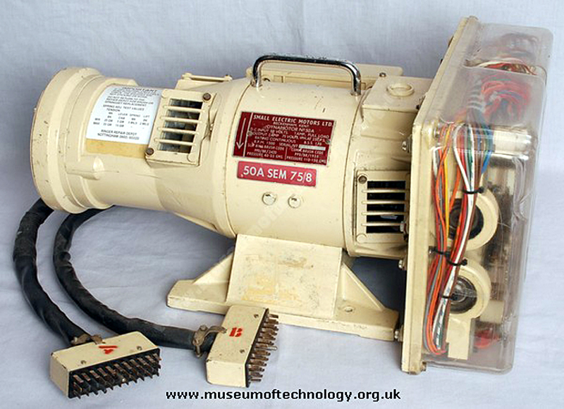 The ring cadence on a 2000-type SxS exchange was a sequence of 400ms ON, 200ms OFF, 400ms ON, 2sec OFF whereas the US Automatic Electric (SxS) and Bell/Western Electric (SxS & Panel) exchanges was 2sec ON, 4sec OFF. In theory the ring power was only switched to the called line at the start of the sequence so that there was not a long first ring however on pre 2000-type or if the exchange was experiencing heavy traffic the ring could switch in at the wrong point in the sequence resulting in a long first ring. I don’t know if the Bell/Western Electric exchanges had an intentional long first ring. As mentioned by Clive, ring trip on a pre 2000-type and 2000-type SxS exchange was achieved by having the ring go through a slugged relay (H-Rly) in the Final Selector. The ring was imposed on a DC feed. The H-Rly was ‘slugged’ so it did not ‘chatter’ on the AC but when the handset was lifted looping the line, there was a DC path of about 200R and the H-Rly operated disconnecting the ring. For experimental purposes this sort of ring-trip can be achieved using a 12V 300-400R DPDT relay, a capacitor and a 1N4007 diode. Below is a circuit that I adapted from the Link PAX design. The first image shows the circuit in the ringing state and the second image shows when the line is looped to allow a DC path. My change from the original design was to use the second set of contacts to make the relay hold on the 24V DC as soon as it operates. 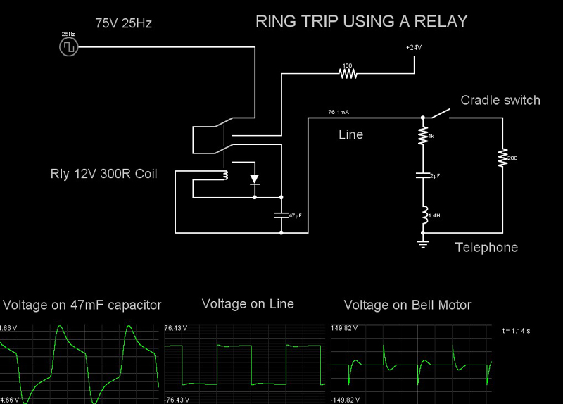 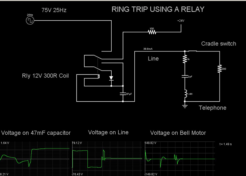 An alternative ring-trip using a transistor is taken from a very useful document, TELECOM DESIGN TRICKS, free from Cambridge Electronics Laboratories (http://www.camblab.com/lit/lit.htm). This allows easy interfacing with a microprocessor. 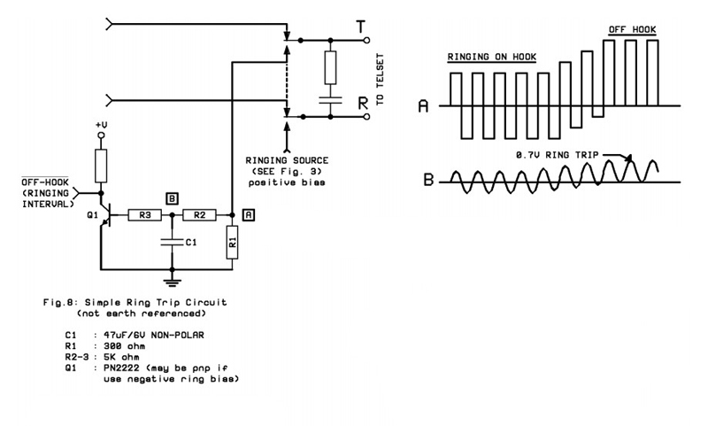 Andrew |
|
|
Return to top of page · Post #: 29 · Written at 1:37:14 AM on 8 October 2015.
|
|
|
|
Location: Somewhere, USA
Member since 22 October 2013 Member #: 1437 Postcount: 896 |
|
Yes it would be a little easy with a micro (again) you could use an ADC and look at the ringer circuit indirectly with that. |
|
|
Return to top of page · Post #: 30 · Written at 6:30:23 PM on 12 December 2015.
|
|
|
|
Location: Toowoomba, QLD
Member since 1 December 2015 Member #: 1834 Postcount: 42 |
|
"When ever someone rang him his poor old dog would get a 100 volt charge through him because he was chained to the fence lol." |
|
|
You need to be a member to post comments on this forum.
|
|


Sign In
Vintage Radio and Television is proudly brought to you by an era where things were built with pride and made to last.
DISCLAIMER: Valve radios and televisions contain voltages that can deliver lethal shocks. You should not attempt to work on a valve radio or other electrical appliances unless you know exactly what you are doing and have gained some experience with electronics and working around high voltages. The owner, administrators and staff of Vintage Radio & Television will accept no liability for any damage, injury or loss of life that comes as a result of your use or mis-use of information on this website. Please read our Safety Warning before using this website.
WARNING: Under no circumstances should you ever apply power to a vintage radio, television or other electrical appliance you have acquired without first having it checked and serviced by an experienced person. Also, at no time should any appliance be connected to an electricity supply if the power cord is damaged. If in doubt, do not apply power.
Shintara - Keepin' It Real · VileSilencer - Maintain The Rage