
Vintage Telephones
Forum home - Go back to Vintage Telephones
|
Compact PBX Ring Generator
|
|
|
Return to top of page · Post #: 16 · Written at 12:18:04 AM on 16 February 2014.
|
|

|
Location: Sydney, NSW
Member since 28 January 2011 Member #: 823 Postcount: 6687 |
|
Thanks for that history RA. Your mention of tuned transformer in telephony jogged a vague memory from 40 years ago of reading about those. |
|
|
Return to top of page · Post #: 17 · Written at 4:43:32 PM on 18 February 2014.
|
|

|
Location: Silver City WI, US
Member since 10 May 2013 Member #: 1340 Postcount: 977 |
|
Yes, thanks for the info RA, I'm always curious about apparatus that existed in those red brick buildings where the public were not allowed to peek in! |
|
|
Return to top of page · Post #: 18 · Written at 10:51:40 PM on 18 February 2014.
|
|

|
Administrator
Location: Naremburn, NSW
Member since 15 November 2005 Member #: 1 Postcount: 7301 |
|
For those unaware, Western Electric and Standard Telephones and Cables (STC) were related companies. The font used for the printing of the names of both companies was the same. STC is now part of Nortel and STC Australia was swallowed by Alcatel in the early 1990s. ‾‾‾‾‾‾‾‾‾‾‾‾‾‾‾‾‾‾‾‾‾‾‾‾‾‾‾‾‾‾‾‾‾‾‾‾‾‾‾‾‾‾‾‾‾‾‾‾‾‾‾‾‾‾‾‾‾‾‾‾‾‾‾‾‾‾‾‾ A valve a day keeps the transistor away... |
|
|
Return to top of page · Post #: 19 · Written at 10:19:16 AM on 19 February 2014.
|
|

|
Location: Canberra, ACT
Member since 24 April 2012 Member #: 1136 Postcount: 168 |
|
Further to the question of how were ringing and tones produced, I have scanned two pictures of STC PAX equipment from a 1947 brochure. The associated text states that, “Ringing and tones are generated by means of a 2½ watt battery-driven ringing machine of the tone inductor type or alternatively by a ringing vibrator operating at the exchange voltage. Vibrators are employed only on the smaller units.” 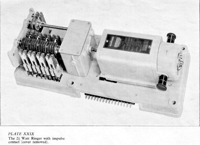 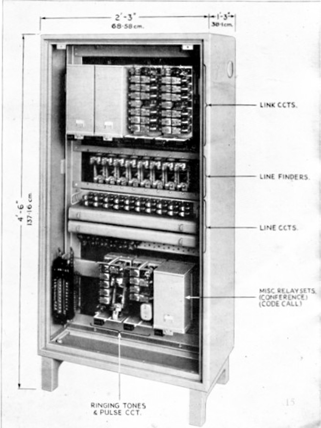 The first picture shows the ringing machine which seems to be a DC motor/generator that also drives two sets of cams through a reduction gearbox. The cams then operated spring-sets to get the required cadences. Assuming that the plug contact strip was the same as that on a relay set, then the whole unit would have been about 18-20 inches long. (And probably very heavy judging by the cast iron base plate; note the holes for the mounting bolts.) The second picture shows a 25-line PAX with a vibrator arrangement in the bottom section of the cabinet. The original photograph is rather poor but the two relays at the top of each relay set appear to be the vibrators with the other relays probably generating the timing of tones. There seems to be a uniselector in the left hand set that would have produced the ringing cadence. The AE sub-cycle ringer can be seen at: http://www.telephonecollectors.info/index.php/bruce-crawford-library/doc_view/1509-ae-bulletin-444-sub-cycle. The D-35237A unit was used by the PMG in Australia at one stage. I 'recovered' one from a PABX room in a disused building just before it was demolished. The building was part of what had been a WWII ammunition factory. Connected to a 240V/110V step-down transformer (borrowed from an old Bell and Howell 16mm projector) it worked for a while until the insulation on the main transformer broke down making the chassis 'live' and too dangerous to use. Andrew |
|
|
Return to top of page · Post #: 20 · Written at 10:34:22 AM on 19 February 2014.
|
|
|
|
Location: Canberra, ACT
Member since 24 April 2012 Member #: 1136 Postcount: 168 |
|
From GTC "The Spence Electronics box looks interesting, but the "standard" model strikes me as more a ring relayer than generator as it needs a PBX ring current as input." |
|
|
Return to top of page · Post #: 21 · Written at 11:12:51 AM on 19 February 2014.
|
|
|
|
Location: Cameron Park, NSW
Member since 5 November 2010 Member #: 770 Postcount: 387 |
|
While my main interest is old radios, I do have one phone, given to me with a radio I purchased. |
|
|
Return to top of page · Post #: 22 · Written at 8:50:42 PM on 20 February 2014.
|
|
|
|
Location: Canberra, ACT
Member since 24 April 2012 Member #: 1136 Postcount: 168 |
|
After some digging I found the 25Hz ringing converter that I previously mentioned. It was made in 1974 which was later than I thought but I have seen the same arrangement built into other power supplies for PMBX (cordless switchboards) from the 1960s. 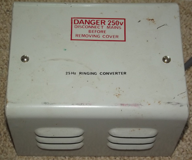 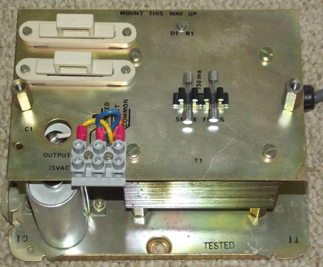 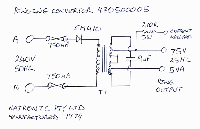 This unit still works but having DC on the primary side rather upsets the safety breaker in the switchboard. Andrew |
|
|
Return to top of page · Post #: 23 · Written at 10:29:02 PM on 21 February 2014.
|
|
|
|
Location: Canberra, ACT
Member since 24 April 2012 Member #: 1136 Postcount: 168 |
|
Further to the 25Hz Ringing Converter, I found a reference to similar units used by the BPO in Britain in the 1960s on Bob Freshwater's excellent site. See: |
|
|
Return to top of page · Post #: 24 · Written at 5:29:17 PM on 23 February 2014.
|
|
|
|
Location: Silver City WI, US
Member since 10 May 2013 Member #: 1340 Postcount: 977 |
|
I was wondering how they did it, those intriguing circuits revealing! |
|
|
You need to be a member to post comments on this forum.
|
|

Sign In
Vintage Radio and Television is proudly brought to you by an era where things were built with pride and made to last.
DISCLAIMER: Valve radios and televisions contain voltages that can deliver lethal shocks. You should not attempt to work on a valve radio or other electrical appliances unless you know exactly what you are doing and have gained some experience with electronics and working around high voltages. The owner, administrators and staff of Vintage Radio & Television will accept no liability for any damage, injury or loss of life that comes as a result of your use or mis-use of information on this website. Please read our Safety Warning before using this website.
WARNING: Under no circumstances should you ever apply power to a vintage radio, television or other electrical appliance you have acquired without first having it checked and serviced by an experienced person. Also, at no time should any appliance be connected to an electricity supply if the power cord is damaged. If in doubt, do not apply power.
Shintara - Keepin' It Real · VileSilencer - Maintain The Rage