
Vintage Television
Forum home - Go back to Vintage Television
|
Precedent model 459 EHT problem
|
|
|
Return to top of page · Post #: 16 · Written at 7:48:00 AM on 13 June 2019.
|
|

|
Location: Nildottie, SA
Member since 7 April 2018 Member #: 2236 Postcount: 43 |
|
Thanks for that. I had checked the amplitude before but not the frequency or bias. I will go over again more closely. |
|
|
Return to top of page · Post #: 17 · Written at 8:34:56 AM on 13 June 2019.
|
|

|
Location: Werribee South, VIC
Member since 30 September 2016 Member #: 1981 Postcount: 470 |
|
I used to find "Trigon" brand valves to be very hit and miss. |
|
|
Return to top of page · Post #: 18 · Written at 5:49:47 PM on 8 July 2019.
|
|
|
|
Location: Nildottie, SA
Member since 7 April 2018 Member #: 2236 Postcount: 43 |
|
Ok, replaced CRT and tried a different EHT winding with no difference. Finally realised that with a very faint crosshatch visible, some of the LOPT must be working. Bridged the 47K resistor between Brightness and Contrast (already a variant from the diag,), a marked difference but still way too bright. |
|
|
Return to top of page · Post #: 19 · Written at 12:51:34 PM on 9 July 2019.
|
|
|
|
Location: Werribee South, VIC
Member since 30 September 2016 Member #: 1981 Postcount: 470 |
|
That CRT clearly doesn't need an ION trap. If it did it wouldn't have produced a raster without one. |
|
|
Return to top of page · Post #: 20 · Written at 4:46:32 PM on 9 July 2019.
|
|
|
|
Location: Nildottie, SA
Member since 7 April 2018 Member #: 2236 Postcount: 43 |
|
Oh ok. The original tube's gun looked as though it had been damaged, gun at an angle etc. I will post a pic. |
|
|
Return to top of page · Post #: 21 · Written at 8:52:37 AM on 10 July 2019.
|
|
|
|
Location: Nildottie, SA
Member since 7 April 2018 Member #: 2236 Postcount: 43 |
|
Photos here of the gun from the original Precedent CRT and the clamp from around the base. 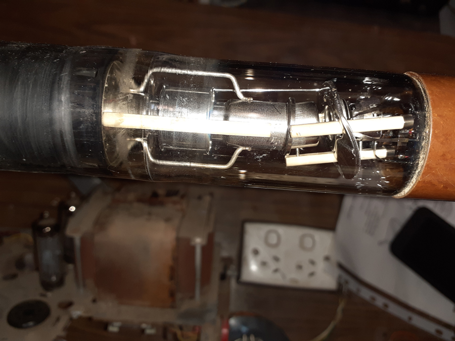 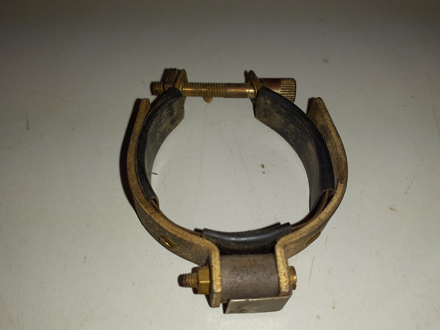 |
|
|
Return to top of page · Post #: 22 · Written at 6:21:40 PM on 12 July 2019.
|
|

|
Administrator
Location: Naremburn, NSW
Member since 15 November 2005 Member #: 1 Postcount: 7301 |
|
Photos uploaded to Post 21. ‾‾‾‾‾‾‾‾‾‾‾‾‾‾‾‾‾‾‾‾‾‾‾‾‾‾‾‾‾‾‾‾‾‾‾‾‾‾‾‾‾‾‾‾‾‾‾‾‾‾‾‾‾‾‾‾‾‾‾‾‾‾‾‾‾‾‾‾ A valve a day keeps the transistor away... |
|
|
Return to top of page · Post #: 23 · Written at 3:38:23 PM on 13 July 2019.
|
|
|
|
Location: Werribee South, VIC
Member since 30 September 2016 Member #: 1981 Postcount: 470 |
|
You can clearly see the offset on the gun assembly. The ION trap bends the electron beam back but the ION's being less affected by the ION trap magnet miss the phosphor altogether. The later phosphors were aluminized and were unaffected by ION's thus the gun assembly is straight. |
|
|
Return to top of page · Post #: 24 · Written at 7:34:59 PM on 13 July 2019.
|
|
|
|
Location: Nildottie, SA
Member since 7 April 2018 Member #: 2236 Postcount: 43 |
|
Thanks for that. I will keep this CRT aside for the future. |
|
|
Return to top of page · Post #: 25 · Written at 9:10:57 AM on 18 July 2019.
|
|
|
|
Location: Nildottie, SA
Member since 7 April 2018 Member #: 2236 Postcount: 43 |
|
Now with a very good clear picture although I don't know why the screen voltage has to be as low as 63V. I am running the input directly into the grid of the video amplifier. |
|
|
Return to top of page · Post #: 26 · Written at 9:41:44 PM on 20 July 2019.
|
|
|
|
Location: Belrose, NSW
Member since 31 December 2015 Member #: 1844 Postcount: 2370 |
|
Yes that is VERY low for the G2. The CRTs beam spot size will be much larger than optimum and beam will spread on highlights, degrading your picture. Try measuring it through a low pass filter of 100k in series with .1μF across the meter. That is likely to be more accurate, G2 might be carrying blanking pulses which will confuse your meter. |
|
|
Return to top of page · Post #: 27 · Written at 1:10:57 PM on 2 December 2019.
|
|
|
|
Location: Nildottie, SA
Member since 7 April 2018 Member #: 2236 Postcount: 43 |
|
Brought this out again to test a recently purchased Dick Smith LOPT tester kit K7205. All coils test ok except the EHT reading bad. I don't know how accurate this would be. |
|
|
Return to top of page · Post #: 28 · Written at 10:38:59 AM on 3 December 2019.
|
|
|
|
Location: Werribee South, VIC
Member since 30 September 2016 Member #: 1981 Postcount: 470 |
|
If an Line O/P transformer has a shorted turn you will get no EHT at all. |
|
|
Return to top of page · Post #: 29 · Written at 9:58:02 AM on 4 December 2019.
|
|
|
|
Location: Nildottie, SA
Member since 7 April 2018 Member #: 2236 Postcount: 43 |
|
The cct. diagram shows the CRT as 21CBP4. |
|
|
Return to top of page · Post #: 30 · Written at 10:38:38 AM on 4 December 2019.
|
|
|
|
Location: Werribee South, VIC
Member since 30 September 2016 Member #: 1981 Postcount: 470 |
|
What happens to the voltage on the anode of the video o/p tube if the CRT socket is unplugged? |
|
|
You need to be a member to post comments on this forum.
|
|
Sign In
Vintage Radio and Television is proudly brought to you by an era where things were built with pride and made to last.
DISCLAIMER: Valve radios and televisions contain voltages that can deliver lethal shocks. You should not attempt to work on a valve radio or other electrical appliances unless you know exactly what you are doing and have gained some experience with electronics and working around high voltages. The owner, administrators and staff of Vintage Radio & Television will accept no liability for any damage, injury or loss of life that comes as a result of your use or mis-use of information on this website. Please read our Safety Warning before using this website.
WARNING: Under no circumstances should you ever apply power to a vintage radio, television or other electrical appliance you have acquired without first having it checked and serviced by an experienced person. Also, at no time should any appliance be connected to an electricity supply if the power cord is damaged. If in doubt, do not apply power.
Shintara - Keepin' It Real · VileSilencer - Maintain The Rage