Welcome to Australia's only Vintage Radio and Television discussion forums. You are not logged in. Please log in below, apply for an account or retrieve your password.
Australian Vintage Radio Forums
  Home  ·  About Us  ·  Discussion Forums  ·  Glossary  ·  Outside Links  ·  Policies  ·  Services Directory  ·  Safety Warnings  ·  Tutorials

Member Introductions

Forum home - Go back to Member Introductions

 Young Newbie with a STC Console Radio
« Back · 1 · 2 · Next »
 Return to top of page · Post #: 1 · Written at 3:31:51 PM on 20 February 2018.
HankKitts's Gravatar
 Location: Coffs Harbour, NSW
 Member since 20 February 2018
 Member #: 2212
 Postcount: 2

So yesterday I was walking through a second hand shop and spotted a large console radio and bought it on a whim.
I don't collect radios so I'm not too sure what I've gotten myself into but I was looking for a project to work on in my spare time.
After some research I've found out that it is a 780B Ch= 78B model Standard Telephones and Cables from about 1936 apparently.
Not sure how rare or desirable STC radios are.

I think its veneered and the veneer still seems relatively intact. In fact it seems to be in pretty decent but not great condition.
It still has most of its stickers and such still intact in the case and none of the wires appear damaged.

Didn't try to power it up and all I've done so far is carefully removed the electronics from it and removed the broken down wadding.
Not sure how to even begin going about restoring it so I guess I've got a lot to learn. Any basic tips would be helpful.

STC console radio
STC console radio
STC console radio
STC console radio


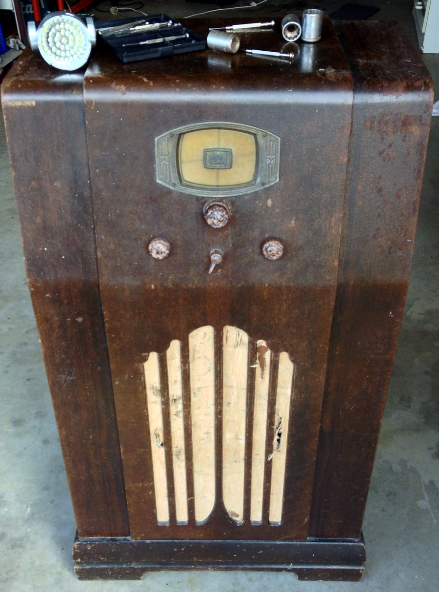
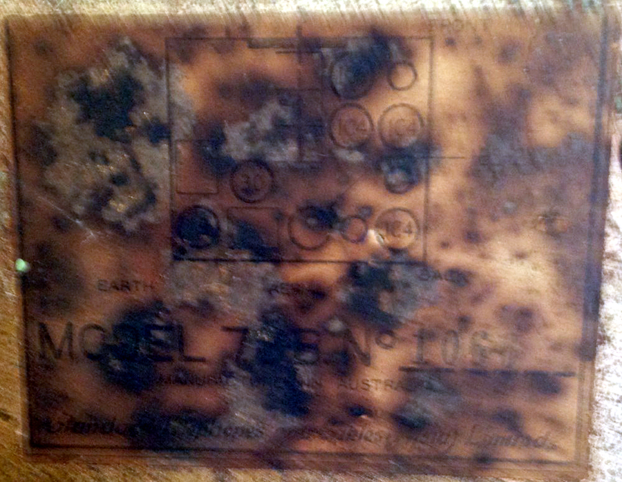
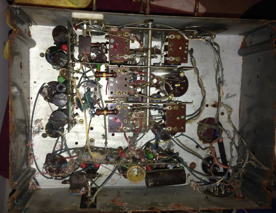
 Return to top of page · Post #: 2 · Written at 5:13:08 PM on 20 February 2018.
Johnny's avatar
 Location: Hobart, TAS
 Member since 31 July 2016
 Member #: 1959
 Postcount: 544

Welcome HankKitts,
If you wish to restore then there are plenty of helpful people on this forum.
With both cabinet and electronic repairs.
You did not mention what your background is so without knowing, it may be an easy project or may be just not a good idea.
Anyway, firstly do not be tempted at this stage to power it up.
Upload good quality images so the experts can have a close peek.
Shots from underneath the chassis as well, and the valve line up.
Then you should be steered to the next step.
If you have never done this sort of thing before, my advice would be to get a 1950's radio first to practice on.
JJ


 Return to top of page · Post #: 3 · Written at 6:42:09 PM on 20 February 2018.
GTC's avatar
 GTC
 Location: Sydney, NSW
 Member since 28 January 2011
 Member #: 823
 Postcount: 6685

Welcome to V-R.

If it's indeed a model 780B, then it's originally a battery set powered by 3 x 45 volt and 2 and 9 volt batteries. If it has a mains cord on it now then it must have been converted for mains use at some stage -- assuming that it's indeed a 780B that you have.

Let us know the valve types in it for a better chance at identification.

Once it's positively identified, then start a thread under that model name in the Tech Talk section to discuss restoration, etc.


 Return to top of page · Post #: 4 · Written at 10:58:43 PM on 20 February 2018.
Brad's avatar
 Administrator
 Location: Naremburn, NSW
 Member since 15 November 2005
 Member #: 1
 Postcount: 7295

Photos uploaded.


‾‾‾‾‾‾‾‾‾‾‾‾‾‾‾‾‾‾‾‾‾‾‾‾‾‾‾‾‾‾‾‾‾‾‾‾‾‾‾‾‾‾‾‾‾‾‾‾‾‾‾‾‾‾‾‾‾‾‾‾‾‾‾‾‾‾‾‾
A valve a day keeps the transistor away...

 
 Return to top of page · Post #: 5 · Written at 11:02:36 PM on 20 February 2018.
Brad's avatar
 Administrator
 Location: Naremburn, NSW
 Member since 15 November 2005
 Member #: 1
 Postcount: 7295

Not sure how rare or desirable STC radios are.

With radios, beauty is in the eye of the beholder. I'm watching an STC radio on Ebay at the moment. If I win it I will post a picture in General Discussion once I've received it.

One of the buildings at STC's Alexandria, NSW radio factory still stands today, converted to a block of flats. It is a short walk from Green Square Railway Station. A close look at the front of the building, you can just see "Standard Telephones and Cables" in the familiar font.


‾‾‾‾‾‾‾‾‾‾‾‾‾‾‾‾‾‾‾‾‾‾‾‾‾‾‾‾‾‾‾‾‾‾‾‾‾‾‾‾‾‾‾‾‾‾‾‾‾‾‾‾‾‾‾‾‾‾‾‾‾‾‾‾‾‾‾‾
A valve a day keeps the transistor away...

 
 Return to top of page · Post #: 6 · Written at 11:32:51 PM on 20 February 2018.
GTC's avatar
 GTC
 Location: Sydney, NSW
 Member since 28 January 2011
 Member #: 823
 Postcount: 6685

OK, the photos show it's a 78B whose valve line up should be: 1C4 1C6 1C4 1C4 1B5 30 19 and according to Radiomuseum data it's a superhet with RF-stage; ZF/IF 450 kHz; 3 AF stage(s).

The Radiomuseum entry lacks photos, and I'm sure yours would be uploaded if you give permission.


 Return to top of page · Post #: 7 · Written at 11:36:52 PM on 20 February 2018.
Ian Robertson's Gravatar
 Location: Belrose, NSW
 Member since 31 December 2015
 Member #: 1844
 Postcount: 2369

Yes, this is a battery radio. It is NOT mains operated. It's what is known as a Farm radio or Bush radio, for use where there was no mains electricity. My small collection is mainly bush radios.

It needs 135V and 2V.

I can help you with a battery eliminator for this radio.

Battery radios sometimes don't need all the paper capacitors changed, although it's still a good idea to do so.

Can you read a circuit diagram? If so, that would be a good start.

I had a look on Kevin Chant's site and I can't see a circuit for a 78B but STC were a bit strange with their model numbers so I'm sure there would be something there with that valve lineup, the same thing with a different number. Here is another reference:

http://www.hws.org.au/RadioHistory/manufacturers/STC.htm

I can't quite make out all the valve types from the chassis legend but it looks like this: (edit) (edit)

1C4 - RF amp (remote cutoff RF pentode)
1C6 - mixer (pentagrid)
1C4 - 1st IF amp (remote cutoff RF pentode)
1C4 - 2nd IF amp (remote cutoff RF pentode)
1B5 - Detector, 1st audio (triode, 2 diodes)
30 - 2nd audio (single triode)
19 - Audio output PP (twin triode)

It should be a hot performer (for a battery set) when restored. Unusually, it's a "dual wave" set, i.e. it has a short wave band.

I've never seen one of these before but that doesn't mean it's a "desirable" model. Desirability is in the eye of the beholder.

Vintage Pete would be able to help you with cabinet restoration advice. There are some very good tips from Pete about cabinets on this forum.


 Return to top of page · Post #: 8 · Written at 11:49:46 PM on 20 February 2018.
GTC's avatar
 GTC
 Location: Sydney, NSW
 Member since 28 January 2011
 Member #: 823
 Postcount: 6685

I've quoted the line-up from Radiomuseum in post #6, which also mentions for this model a 9 volt battery, presumably the C supply.


 Return to top of page · Post #: 9 · Written at 12:28:57 AM on 21 February 2018.
Ian Robertson's Gravatar
 Location: Belrose, NSW
 Member since 31 December 2015
 Member #: 1844
 Postcount: 2369

Yes, GTC, I had another look around myself.

The chassis valve legend has the RF amp and the mixer in unexpectedly-transposed locations.


 Return to top of page · Post #: 10 · Written at 1:03:59 AM on 21 February 2018.
Robbbert's avatar
 Location: Hill Top, NSW
 Member since 18 September 2015
 Member #: 1801
 Postcount: 2012

Interesting old radio. The underside view looks ok, although I'd consider replacing all those black capacitors.

The main thing is that when you are eventually in a position to apply power, is to not accidently apply the wrong voltage to the filaments, or you can say goodbye to a bunch of valves. Be very careful.


 Return to top of page · Post #: 11 · Written at 1:22:14 AM on 21 February 2018.
Ian Robertson's Gravatar
 Location: Belrose, NSW
 Member since 31 December 2015
 Member #: 1844
 Postcount: 2369

That's always an issue with battery valves, which is why when I designed my battery valve power supply I deliberately current-limited the B+ and made the A+ supply very low impedance so such accidents can't happen.

The worst you can do is burn out a 1 cent resistor in the power supply, which will sacrifice itself to protect the radio if the condition lasts for more than a few seconds..

Otherwise, it's all too easy to slip with a meter probe and short the B+ to the A+!


 Return to top of page · Post #: 12 · Written at 5:05:38 AM on 21 February 2018.
MonochromeTV's avatar
 Location: Melbourne, VIC
 Member since 20 September 2011
 Member #: 1009
 Postcount: 1181

Schematic here on Paul Ledger's site.

http://www.thebakeliteradio.com/Circuits/STC/


 Return to top of page · Post #: 13 · Written at 9:35:41 AM on 21 February 2018.
Ian Robertson's Gravatar
 Location: Belrose, NSW
 Member since 31 December 2015
 Member #: 1844
 Postcount: 2369

Well spotted!

There are two interstage audio transformers and a centre-tapped speaker transformer. Those interstage transformers typically use very fine wire internally and may well be open circuit by now. The first one at least could be replaced with R/C coupling with a little gain loss, but there is already more audio gain than you could ever possibly use....


 Return to top of page · Post #: 14 · Written at 2:06:22 PM on 22 February 2018.
HankKitts's Gravatar
 Location: Coffs Harbour, NSW
 Member since 20 February 2018
 Member #: 2212
 Postcount: 2

Thanks for all the help so far, most of the wiring is pretty tattered so I'll have to fix that up before I begin figuring out what to do next.
I'm not going to jump in on anything before I know what I'm doing so I don't do something I shouldn't.
So far the only thing I've done is strip and clean the radio and I'm still figuring out how to go about re-coating the cabinet. Its either reapply the nitrocellulose or go with an alternative like polyurethane.

I know that nitro can be dangerous to apply, takes a long time to apply and haven't got an air conditioner and its not very resistant to heat so that's the main path I'm going to have to figure out for now.

Oh and I'm fine with the photos being used on any website.


 Return to top of page · Post #: 15 · Written at 2:42:06 PM on 22 February 2018.
Ian Robertson's Gravatar
 Location: Belrose, NSW
 Member since 31 December 2015
 Member #: 1844
 Postcount: 2369

Vintage Pete is the expert around these parts.

Read his cabinet repairs posts. The choice to use polyurethane is a pragmatic one, not original, but it can look very nice and it's tough.

Are you planning to do a full bare metal chassis resto? That set is a candidate if you want to put the time in. You can make it look like brand new.

I've done a few such chassis restos. They are very rewarding to do. Here are some clues:

1. Take LOTS of detailed, close-up pictures! Take more as you do the strip-down.

2. The valve sockets on that set come out through the bottom, which means you can pull most of the wiring out in one piece without cutting or unsoldering too much. When re-assembling use pop rivets with flat washers on the socket side.

3. Make a diagram and mark / tag everything with where it goes.

4. Take the bare chassis with you to an automotive spares shop or hardware shop to match the paint colour.

5. Wire brush or bead blast the chassis, removing all the paint and rust. Give it a couple of coats of paint.

6. Use new nuts and bolts but please DON'T use Philips head screws! They weren't invented then.

There is no mains transformer in that set but I'd recommend that, after testing for continuity, you give the two interstage transformers a good soak in Instant Estapol clear lacquer. NOT the water-cleanup stuff! If a transformer has an O/C winding you shouldn't waste your time with it but consider getting it rewound or bypassing it - possible with the first transformer.

You can use software to make replicas of the chassis labels. I have a Word / Open Office file of the ARTS&P transfer if you want it. You'll need a printer that can print colour onto a transparency.

That should be enough to keep you going for a while!


« Back · 1 · 2 · Next »
 You need to be a member to post comments on this forum.

Sign In

Username:
Password:
 Keep me logged in.
Do not tick box on a computer with public access.