
Tech Talk
Forum home - Go back to Tech talk
|
Intermediate Frequency for an Essanay Bantum
|
|
|
Return to top of page · Post #: 1 · Written at 10:24:19 PM on 8 January 2018.
|
|
|
|
Location: Hobart, TAS
Member since 6 May 2013 Member #: 1337 Postcount: 73 |
|
I have an Essanay Bantum that needs an alignment. Would anyone know the intermediate frequency for this receiver? It is a 1937 model with the following valve lineup: 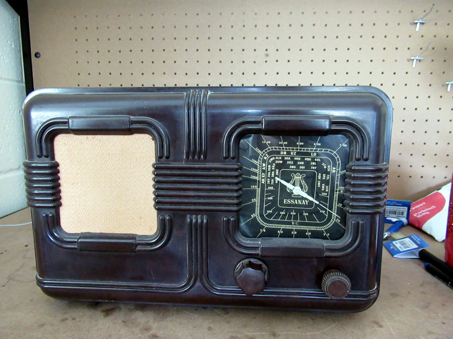 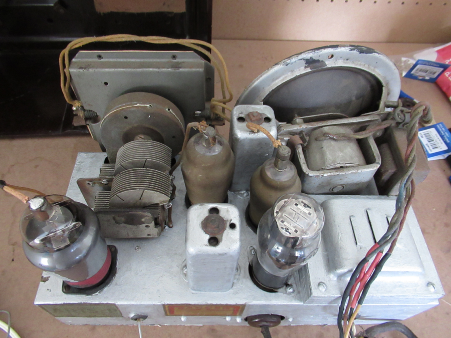 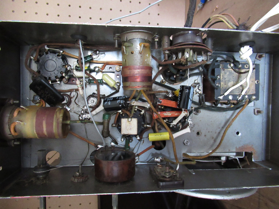 |
|
|
Return to top of page · Post #: 2 · Written at 10:56:08 PM on 8 January 2018.
|
|

|
Location: Sydney, NSW
Member since 28 January 2011 Member #: 823 Postcount: 6956 |
|
Are you sure that's the correct line-up? |
|
|
Return to top of page · Post #: 3 · Written at 11:37:02 PM on 8 January 2018.
|
|

|
Location: Wangaratta, VIC
Member since 21 February 2009 Member #: 438 Postcount: 5720 |
|
I have issues with that as well. |
|
|
Return to top of page · Post #: 4 · Written at 4:11:58 PM on 9 January 2018.
|
|
|
|
Location: Hobart, TAS
Member since 6 May 2013 Member #: 1337 Postcount: 73 |
|
The radio is a bit of a mystery. It is dated at 1937 by the letter D on the licence transfer on the back. The radio is in a Bakelite cabinet with Essanay on the dial below a symbol of a Lyre. I assumed it was a bantam as that was the only model listed on Radio Museum that was produced in 1937 before Essanay ceased production, however it does not match the circuit for the Bantam. The radio appears to be factory wired for an EBL1 as the op valve as the grid is wired to the cap. The AF3 and AK2 were installed in the radio when I found it, however there is the possibility that they are the incorrect valve. I will study the wiring against the valve data. The rectifier valve is an 80 with a UX base instead of the EZ2 on the circuit diagram for the bantam which has the phillips side contact base. |
|
|
Return to top of page · Post #: 5 · Written at 8:03:39 PM on 9 January 2018.
|
|
|
|
Location: Sydney, NSW
Member since 28 January 2011 Member #: 823 Postcount: 6956 |
|
It may help in identification to send Brad some good clear photos. |
|
|
Return to top of page · Post #: 6 · Written at 9:06:14 PM on 9 January 2018.
|
|
|
|
Location: Linton, VIC
Member since 30 December 2016 Member #: 2028 Postcount: 472 |
|
While on the subject, almost every picture I have sent has been slightly blurred.  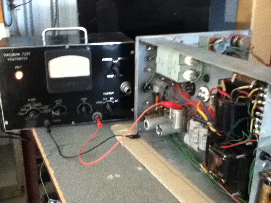 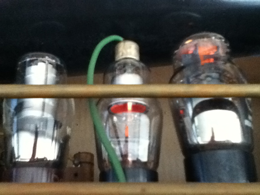 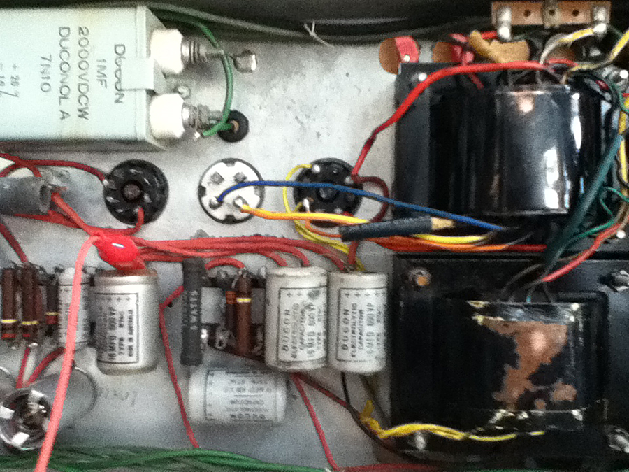 |
|
|
Return to top of page · Post #: 7 · Written at 9:06:37 PM on 9 January 2018.
|
|
|
|
Location: Belrose, NSW
Member since 31 December 2015 Member #: 1844 Postcount: 2711 |
|
You can understand that if the business was in trouble they may have thrown together some radios using what parts they had. I have a built-during-the-war-years STC like that. The model stenciled on the chassis bears no relation to the actual circuit of the radio. |
|
|
Return to top of page · Post #: 8 · Written at 9:59:09 PM on 9 January 2018.
|
|
|
|
Location: Linton, VIC
Member since 30 December 2016 Member #: 2028 Postcount: 472 |
|
Yikes! Sorry everyone. |
|
|
Return to top of page · Post #: 9 · Written at 10:01:57 PM on 9 January 2018.
|
|
|
|
Location: Wangaratta, VIC
Member since 21 February 2009 Member #: 438 Postcount: 5720 |
|
It may have been a victim of the war as well as parts became short. I do get the occasional set where strange mods have been inflicted. |
|
|
Return to top of page · Post #: 10 · Written at 10:12:51 PM on 9 January 2018.
|
|
|
|
Location: Linton, VIC
Member since 30 December 2016 Member #: 2028 Postcount: 472 |
|
Maarc, |
|
|
Return to top of page · Post #: 11 · Written at 10:16:36 PM on 9 January 2018.
|
|
|
|
Location: Sydney, NSW
Member since 28 January 2011 Member #: 823 Postcount: 6956 |
|
|
|
|
Return to top of page · Post #: 12 · Written at 10:26:37 PM on 9 January 2018.
|
|
|
|
Location: Linton, VIC
Member since 30 December 2016 Member #: 2028 Postcount: 472 |
|
Shall do G. |
|
|
Return to top of page · Post #: 13 · Written at 10:50:35 PM on 9 January 2018.
|
|
|
|
Location: Sydney, NSW
Member since 28 January 2011 Member #: 823 Postcount: 6956 |
|
Popular these days is the 'octo' type tripod, such as: |
|
|
Return to top of page · Post #: 14 · Written at 5:28:49 PM on 10 January 2018.
|
|
|
|
Location: Hobart, TAS
Member since 6 May 2013 Member #: 1337 Postcount: 73 |
|
Hi Mark, |
|
|
Return to top of page · Post #: 15 · Written at 9:29:29 PM on 10 January 2018.
|
|

|
Location: Hill Top, NSW
Member since 18 September 2015 Member #: 1801 Postcount: 2256 |
|
I wonder if the rectifier was originally a 4 volt type, something like AZ1 with the 4-pin base? I don't have my valve book with me at present so cannot suggest the correct type, but I'm sure Marcc will know. |
|
|
You need to be a member to post comments on this forum.
|
|
 BringBackTheValve: most modern digital cameras, including those in mobile phones, employ anti-shake technology. I have seen many otherwise in-focus photos ruined by camera shake, so factor that feature into your next camera purchase.
Sign In
Vintage Radio and Television is proudly brought to you by an era where things were built with pride and made to last.
DISCLAIMER: Valve radios and televisions contain voltages that can deliver lethal shocks. You should not attempt to work on a valve radio or other electrical appliances unless you know exactly what you are doing and have gained some experience with electronics and working around high voltages. The owner, administrators and staff of Vintage Radio & Television will accept no liability for any damage, injury or loss of life that comes as a result of your use or mis-use of information on this website. Please read our Safety Warning before using this website.
WARNING: Under no circumstances should you ever apply power to a vintage radio, television or other electrical appliance you have acquired without first having it checked and serviced by an experienced person. Also, at no time should any appliance be connected to an electricity supply if the power cord is damaged. If in doubt, do not apply power.
Shintara - Keepin' It Real · VileSilencer - Maintain The Rage