
Tech Talk
Forum home - Go back to Tech talk
|
Kriesler 11-77/78
|
|
|
Return to top of page · Post #: 61 · Written at 11:32:52 AM on 14 April 2020.
|
|
|
|
Location: Umina Beach, NSW
Member since 9 April 2020 Member #: 2410 Postcount: 33 |
|
Okay so ive been in and had a bit of a look see and removed one end of each resistor to allow for proper testing.Ive measured 4 resistors. |
|
|
Return to top of page · Post #: 62 · Written at 12:02:22 PM on 14 April 2020.
|
|

|
Location: Albury, NSW
Member since 1 May 2016 Member #: 1919 Postcount: 2048 |
|
Ian or someone will tell you which resistors are more likely to cause a crackle in your sound . |
|
|
Return to top of page · Post #: 63 · Written at 12:36:49 PM on 14 April 2020.
|
|
|
|
Location: Toongabbie, NSW
Member since 19 November 2015 Member #: 1828 Postcount: 1250 |
|
Hi Padge, Hint: |
|
|
Return to top of page · Post #: 64 · Written at 12:51:19 PM on 14 April 2020.
|
|
|
|
Location: Albury, NSW
Member since 1 May 2016 Member #: 1919 Postcount: 2048 |
|
Shane, here is my 11 77 chassis I restored. 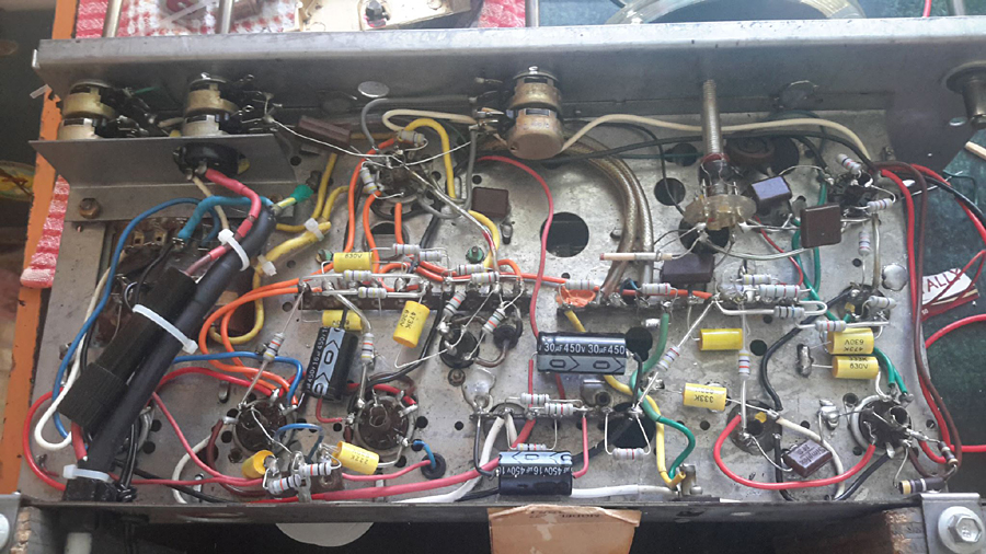 |
|
|
Return to top of page · Post #: 65 · Written at 1:28:55 PM on 14 April 2020.
|
|
|
|
Location: Umina Beach, NSW
Member since 9 April 2020 Member #: 2410 Postcount: 33 |
|
Where did photo send to pete. |
|
|
Return to top of page · Post #: 66 · Written at 1:39:41 PM on 14 April 2020.
|
|
|
|
Location: Umina Beach, NSW
Member since 9 April 2020 Member #: 2410 Postcount: 33 |
|
Thanks for that Fred. I will at least change these 4 resistors that I measured. |
|
|
Return to top of page · Post #: 67 · Written at 1:47:44 PM on 14 April 2020.
|
|
|
|
Location: Belrose, NSW
Member since 31 December 2015 Member #: 1844 Postcount: 2370 |
|
Re-post here in case you missed it: |
|
|
Return to top of page · Post #: 68 · Written at 2:17:40 PM on 14 April 2020.
|
|
|
|
Location: Albury, NSW
Member since 1 May 2016 Member #: 1919 Postcount: 2048 |
|
Shane,yes I have parts. |
|
|
Return to top of page · Post #: 69 · Written at 4:25:52 PM on 14 April 2020.
|
|
|
|
Location: Umina Beach, NSW
Member since 9 April 2020 Member #: 2410 Postcount: 33 |
|
Thanks Ian.Yes I have just done the test. When I turned it on the noise was there. I then removed the 12ax7 in operation the noise went and when I replaced it the noise came back. So is it those 2 mica caps which you said right at the beginning of this whole thread? Or do I need to now measure the voltage across those 2 270k resistors? I guess that is a double check. cheers Ian |
|
|
Return to top of page · Post #: 70 · Written at 4:27:48 PM on 14 April 2020.
|
|
|
|
Location: Umina Beach, NSW
Member since 9 April 2020 Member #: 2410 Postcount: 33 |
|
Thanks Pete, yes I will follow his instructions. |
|
|
Return to top of page · Post #: 71 · Written at 4:56:11 PM on 14 April 2020.
|
|
|
|
Location: Umina Beach, NSW
Member since 9 April 2020 Member #: 2410 Postcount: 33 |
|
Hey Ian I tested the two 270k resistors with the 12ax7 removed and both had voltage. One was 0.55 the other 0.25 so I guess then I will wait for your reply and see if it is what you think. Oh and the power was off too.. |
|
|
Return to top of page · Post #: 72 · Written at 5:18:40 PM on 14 April 2020.
|
|
|
|
Location: Belrose, NSW
Member since 31 December 2015 Member #: 1844 Postcount: 2370 |
|
Replace the resistors. One of them is noisy. You would be wise to replace the two micas as well. |
|
|
Return to top of page · Post #: 73 · Written at 7:47:06 PM on 14 April 2020.
|
|

|
Administrator
Location: Naremburn, NSW
Member since 15 November 2005 Member #: 1 Postcount: 7301 |
|
Photo uploaded to Post 64. ‾‾‾‾‾‾‾‾‾‾‾‾‾‾‾‾‾‾‾‾‾‾‾‾‾‾‾‾‾‾‾‾‾‾‾‾‾‾‾‾‾‾‾‾‾‾‾‾‾‾‾‾‾‾‾‾‾‾‾‾‾‾‾‾‾‾‾‾ A valve a day keeps the transistor away... |
|
|
Return to top of page · Post #: 74 · Written at 7:49:42 PM on 14 April 2020.
|
|
|
|
Location: Albury, NSW
Member since 1 May 2016 Member #: 1919 Postcount: 2048 |
|
Thank you Brad for the fast photo upload, |
|
|
Return to top of page · Post #: 75 · Written at 8:00:20 PM on 14 April 2020.
|
|

|
Location: Hobart, TAS
Member since 31 July 2016 Member #: 1959 Postcount: 544 |
|
Hey Vintage Pete, |
|
|
You need to be a member to post comments on this forum.
|
|
 JJ
JJSign In
Vintage Radio and Television is proudly brought to you by an era where things were built with pride and made to last.
DISCLAIMER: Valve radios and televisions contain voltages that can deliver lethal shocks. You should not attempt to work on a valve radio or other electrical appliances unless you know exactly what you are doing and have gained some experience with electronics and working around high voltages. The owner, administrators and staff of Vintage Radio & Television will accept no liability for any damage, injury or loss of life that comes as a result of your use or mis-use of information on this website. Please read our Safety Warning before using this website.
WARNING: Under no circumstances should you ever apply power to a vintage radio, television or other electrical appliance you have acquired without first having it checked and serviced by an experienced person. Also, at no time should any appliance be connected to an electricity supply if the power cord is damaged. If in doubt, do not apply power.
Shintara - Keepin' It Real · VileSilencer - Maintain The Rage